2004 – 2006
Work Begins (12/7/2004)
The set of plans I ordered from Richard Killen arrived today. My initial order was for sets 1, 2, 3 and 4. The remaining sets (5, 6, and 7) are not quite ready yet. As soon as they are I will get them ordered and cataloged. WOW!! There sure are a lot of drawings.
Final Drawings Arrive (1/15/2005)
The balance of the drawings have arrived. More sorting, reviewing, and cataloging so I can find what I want easily. I have contracted to have the frame side plates laser cut. They should be ready soon and then I can start working on the bent angle iron pieces to rivet to the sides. I am told that there will be about 2,000 rivets in the frame and its various parts before I am finished. Looks like I’ll get real good at riveting!
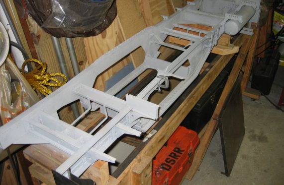
Frame Sides Cut and Ready (2/7/2005)
The frame sides are back from the laser cutter. They sure look nice. Now the fun begins!!
Castings Castings Castings (2/26/2005)
Again this year, I made the trip the Ridge Live Steamers in Florida for their meet. John Johnson of LocoGear brought as many of the castings as he had for me so I saved a bit on shipping when all was said and done. Its not a complete set of castings yet since some of the parts are still waiting for the patterns to be completed. For now, all the castings will be stored for later until I get the frame done.
Frame Sides Started (3/06/2005)
Layout of the rivet holes has been done and drilling is in progress.
 Both plates


Frame Parts Fabrication (3/20/2005)
Work is continuing on the engine frame. Some of the frame spreader parts are nearing completion.
 Cleco usage


Frame Mock-up (6/9/2005)
With most of the frame spreader parts fabricated, it seemed like a good time to put it all together (albeit temporarily) to see what it was going to look like. In this state, its already too heavy for one person to move it around easily.
 Frame mockup assembly


Pilot Beam (6/24/2005)
For the last few days, I’ve been working on all the pieces and parts that make up the locomotive’s pilot beam. It’s a combination of wood and steel to make up the poling pockets, handrails, coupler release rod, and foot boards. It still lacks primer paint, but it’s essentially done.
 Pilot beam with wood and steps
Frame Assembly Begins (7/21/2005)
All of the frame spreader parts and running board supports are completed (except for the after-market frame braces installed by the Western Maryland shop after delivery). So it was time to start assembling the frame which began in earnest today. The pilot beam back-plate was riveted in place about a week ago so the frame brace to it could be measured and welded together. The front draft gear housing was completed 3 days ago so it was time to start working along the frame putting in spreaders as I go. The first spreader is the body bolster for the front truck. It is attached to the rear end of the draft gear housing so its position is dictated strictly by the housing’s length. The draft gear housing is within 0.015 of the design length which is close enough. First the rivet holes were marked on the frame sides using the bolster as the template and then the holes were drilled using a close-quarters drill. When everything was finally in position, the riveting began. There are a total of 48 rivets used to fasten the bolster to the frame sides. It didn’t take very long to complete the riveting using 1/8″ steel rivets in lengths of 1/2″ and 3/8″. A little primer when it was done and voila!…the first spreader is installed. So far…so good!!
 Rivet detail


Frame Assembly Continues (7/30/2005)
Work on the “add-ons” for the frame (running board supports, pump mounting brackets, cab supports, etc.) is continuing. The on-board air tank for the braking system was completed and mounted. Assembly of the pilot beam apparatus has been done. As soon as I can figure out the exact locations of the cab braces they will be mounted. The left side running board brackets have been test fit and removed for primer paint. They should be mounting in a couple of days.
 Air tank on right side


Engine Frame Assembly Complete (10/30/2005)
The engine frame is pretty much complete. I lack the end casting to connect it to the tender. I am waiting for it to be cast and delivered from my supplier.
 Engine frame almost done

Tender Frame Fabrication (8/25/2005)
As I am finishing up the engine frame, I started work on the tender frame. It consists of 4 runners the length of the tender with a draft gear housing at the rear. There are planks on tap that cantilever out beyond the frame on which the tank sits. Update (11/30/2005): The tender frame is complete.
 Tender frame complete


Tender Tank (11/30/2005)
Now that the frame is done, it’s time to start working on the tender tank. I’ve decided to construct it entirely of brass as I have done in the past. Using brass eliminates the risk of any corrosion and I can easily soft solder all the joints to seal it. I’m using a sheet of 16ga for the bottom and 1/2″ angle with 1/8″ wall thickness for the interior frame. I haven’t decided what gauge material I’ll use for the skin of the tank yet. Here are some photos of the work so far. Oh, there is also a picture of the sand box and ladder for the rear of the tender.
 Tender tank framing started


Truck Center Pivots (12/15/2005)
As you can see from the picture, I have fabricated the truck center pivots. This part sits on top of the upper spring plank of the truck and acts as the pivot point for the truck. Three of them are needed. I started with a solid block of aluminum-bronze and using my rotary table on the mill, carved out the pivot as shown.
 Center bolster pivot for tender
Truck Bolsters (Spring Planks) (01/08/2006)
I got tired of working on the tender so I took a break from it and started on the trucks bolters (also called spring planks on a Shay). The upper and lower spring planks are a built-up assembly of steel rectangular tube, steel channel (actually a section of tube cut lengthwise to form two channels), and 1/8″ steel plate. It’s all held together with steel rivets. Only the lower planks are shown In the pictures below…the upper ones aren’t picture-worthy just yet.
 Spring planks
More Tender Tank (04/09/2006)
I’ve actually gotten quite a bit done on the tender tank since my last update about it. The skin is fully attached (500+ copper rivets!) and all the joints have been soldered and sealed. The mounting lugs (front and rear) have also been riveted in place. I created a set of baffles for the inside of the tank and have riveted them in place to the tank bottom. The water outlet holes have been drilled and the bushings have been soldered in place. You can also see in the pictures the first “plumbing” pieces of the project…the tank drain valve! Just a few more details to complete and it will be ready for paint.
 Tender tank gets assembled with clecos


Tender Nears Completion (04/09/2006)
The tender is nearly complete in the pictures below. The final paint has been applied to the tank and frame. A coat of “clear coat” paint is still needed on the tender tank and then I can lash the two pieces together, complete the plumbing for air and water underneath the unit, and mount the hand pump in the tank. I haven’t started on the tender lid yet although I have started the water funnel for it.
 Tender nearly completed


Wheels Wheels Wheels (05/16/2006)
Well I couldn’t put it off any longer. I finally got a lathe chuck (4-jaw) large enough to hold the wheel blank so I decided to turn one to see how it went. The machining instructions from LocoGear were excellent and easy to follow but my poor little lathe made is a struggle. Its only a 9×20 and the 8-inch chuck is a handful. Altogether, it took a little over 10 hours of work to machine both sides of the wheel. Sometimes it felt like I was watching paint dry making some of the cuts. The cuts had to be rather light to accommodate my lathe’s size. I still have to put the wheel in the mill and drill/tap all the holes and machine out the bolt protectors. Then I’ll only have 11 more wheels to do.
 Driver wheel bring machined


Boiler Mockup (05/07/2006)
For giggles, I thought I’d make a wooden mockup of the boiler to see how it fit in the frame and also get a feel for its size. It fit in the frame really well (was I surprised?) and is HUGE! I guess I won’t be picking up the real one by myself.
 Fake boiler in loco frame

Tender Funnel (05/20/2006)
I finally spent a little time working on the fabrication of the funnel for the tender tank. It was fabricated entirely of brass in multiple pieces and then soldered and riveted together. I think it came out rather well.
 Tender water funnel

Final Tender Tank (06/30/2006)
The tender is nearly complete. The tanks is assembled, the top is made, the funnel is installed, the sand box is installed, the ladder is installed and the whole thing has been primed and finish painted (including 2 coats of clearcoat). It looks pretty nice. Of course, there aren’t any trucks for it yet and I haven’t installed the brake cylinder even though it is complete. I have the rear-facing headlight made but not mounted. All the plumbing (air and water) is in place and ready for attachment to the engine.
 Tender with Sander
Brake Shoes (07/12/2006)
In my spare time I’ve also been working on the brake rigging. I have the brake beams done as well as all the levers and hangers for the mechanism. I started working on the brake shoes by turning 2 rings of blanks with the proper radius. Now they need to be cut out and have the lining attached.
OK…it’s been a while since I updated the this information. So here is the skinny one what’s been happening.
 Machining a ring of brake shoes

Cab Floor (07/18/2006)
I started work on the cab. Here is the first look at the start of it.
 Start of the cab floor
Fuel Bunker (08/22/2006)
I needed something to sit on top of my cab floor so I have started forming the fuel bunker walls. I’m not planning to put all the bracing inside the fuel bunker that the original had so it could hold coal. I plan to fuel mine with fuel oil so there will be an oil tank fitted inside the fuel bunker and I want to maximize the available space. After getting the fuel bunker pretty much done I moved forward to work on the cab walls. One thing that I am doing with the cab floor and cab proper is making it so that it can be removed for servicing without having to dismantle a whole bunch of plumbing, etc. It should make future maintenance and upgrades easier in the future.
 Fuel bunker frame


Fire Box Door (10/20/2006)
I took a bit of a break from the cab work to machine and assemble the fire box door that I will be using. Wayne gave me a set of castings that he found buried on a shelf for a butterfly door that is prototypical for WM6. It took a bit of doing but I have it working. It will have a floor-mounted actuator that the fireman would have stepped on to open the doors to feed coal. I’ll just press it with my finger but the principle is the same.
 Firebox door


Cab Walls and Windows (11/18/2006)
I have working 3-pane windows on both sides of the cab (with glass) and have the two non-operating windows (with glass) in the front wall of the cab. The glass isn’t installed yet in the pictures below. I have completed the side walls and windows (actually in December 2006) as you can see in the pictures. The third picture shows the window rails before mounting around the cab windows. The front wall is also done including the windows. I haven’t as yet assembled the entire cab into a single unit as I am waiting to finish the under-cab plumbing after which I can paint the frame and then mount the cab floor in its permanent position.
 Cab front


Under-Cab Plumbing (12/02/2006)
The under-cab plumbing which includes the water lines for 2 injectors and a hand pump and compressed air brake lines has been completed. I have plumbed the brake lines for engine brakes and separate train brakes. I have also allowed for dual air supply inputs. One will be the the on-board air reservoir serviced by an on-board steam-driven air pump and the other can be an out-board air pump supply from a trailing box car or other source. This way the engine will be able to operate completely “stand-alone” and self-contained, or if desired, I can couple up my service box car which acts as a compressed air source and electrical supply to the train. Now if it will all work as I planned.
 Plumbing under the cab floor

