Introduction
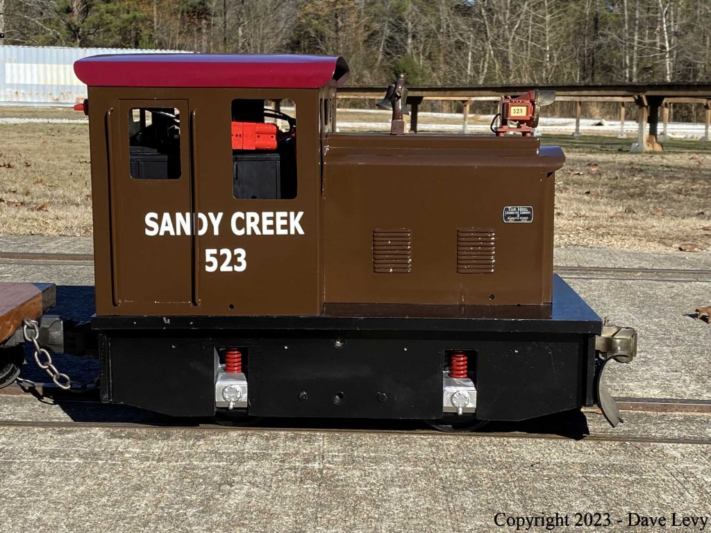
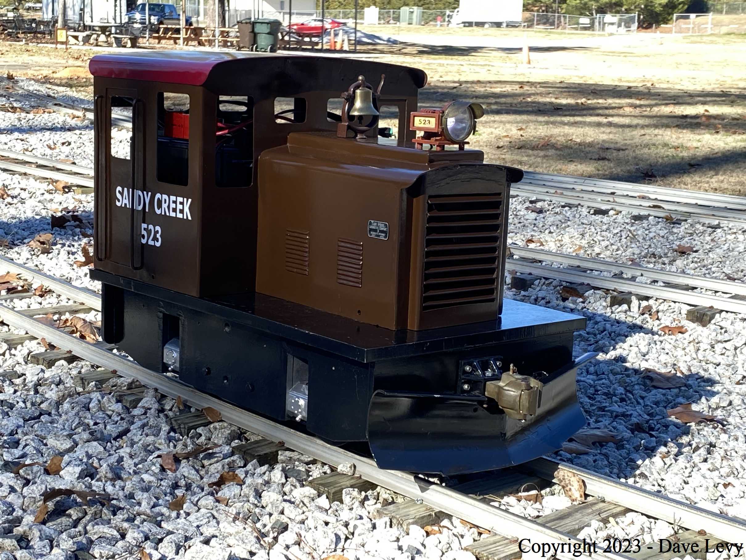
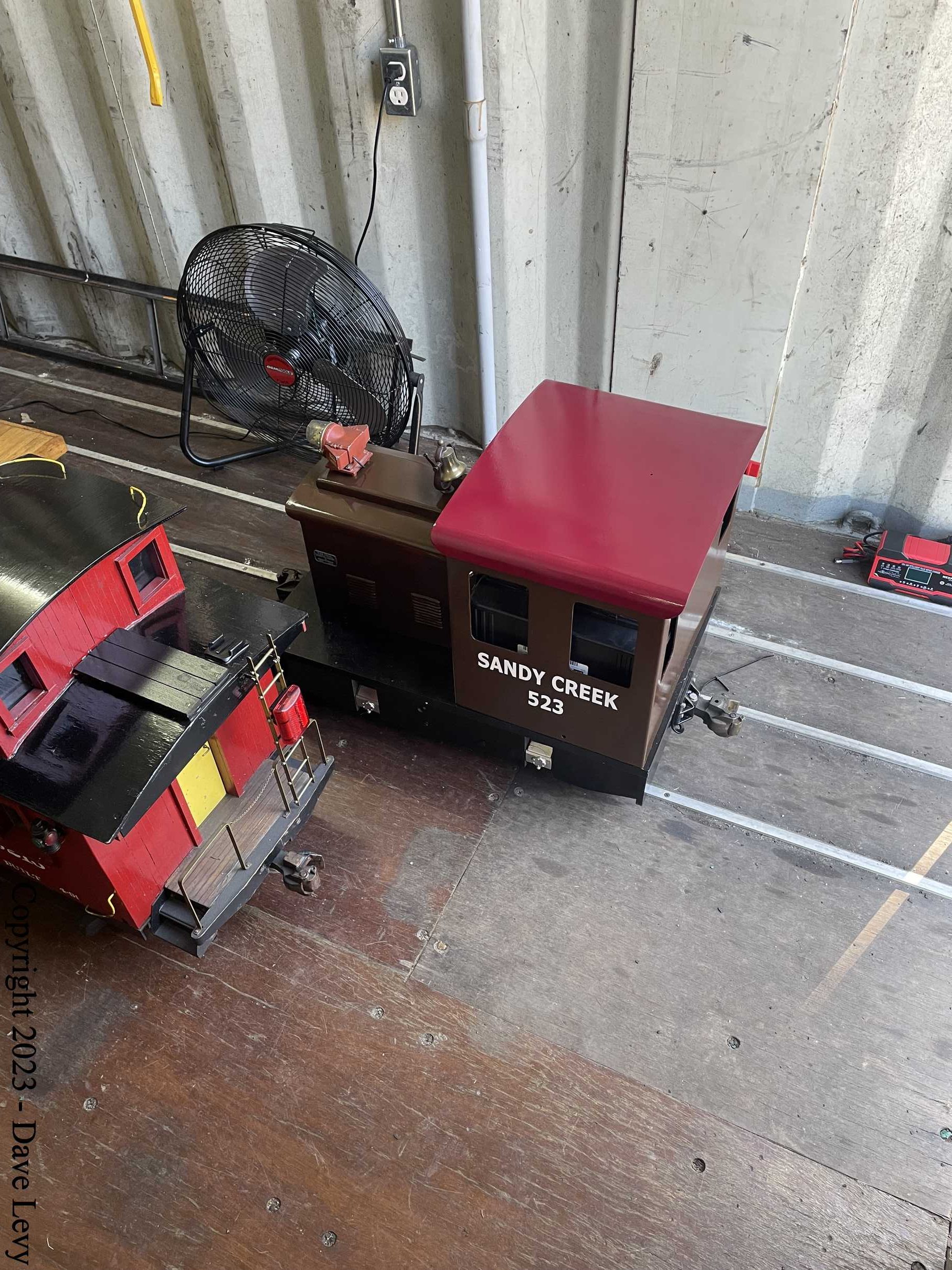
I needed a project to work on so I decided to restore an old switcher engine that had been in storage for 20+ years. This is the story of that restoration effort.
Switcher History
The story begins 40+ years ago when the switcher was built by Paul Demianchik in about 1979. The cab was custom built for him by Bill Koster’s Miniature Railroad Supply. The motor and controller also came from Bill. The drive train came from Railroad Supply Corp. The exact origin of the chassis is unknown. When Paul unexpectedly passed away, his widow (Darlene) gave the loco to John Lass, son of Wayne Lass. When John Lass was tragically killed in an auto accident in 1995, the loco went back to Darlene. This is about the time (1997ish) that I first came into contact with the switcher. I can recall (vaguely) that it ran a few times at Wayne’s home track but not more than a couple of times. The electronics were, by then, very old and a fresh 12V battery was something of a rarity at the time. The switcher spent many years after that languishing on a storage shelf in Wayne’s basement, to be seen only occasionally when it was deemed to be “in the way” and needed to be shuffled around.
Restoration Begins
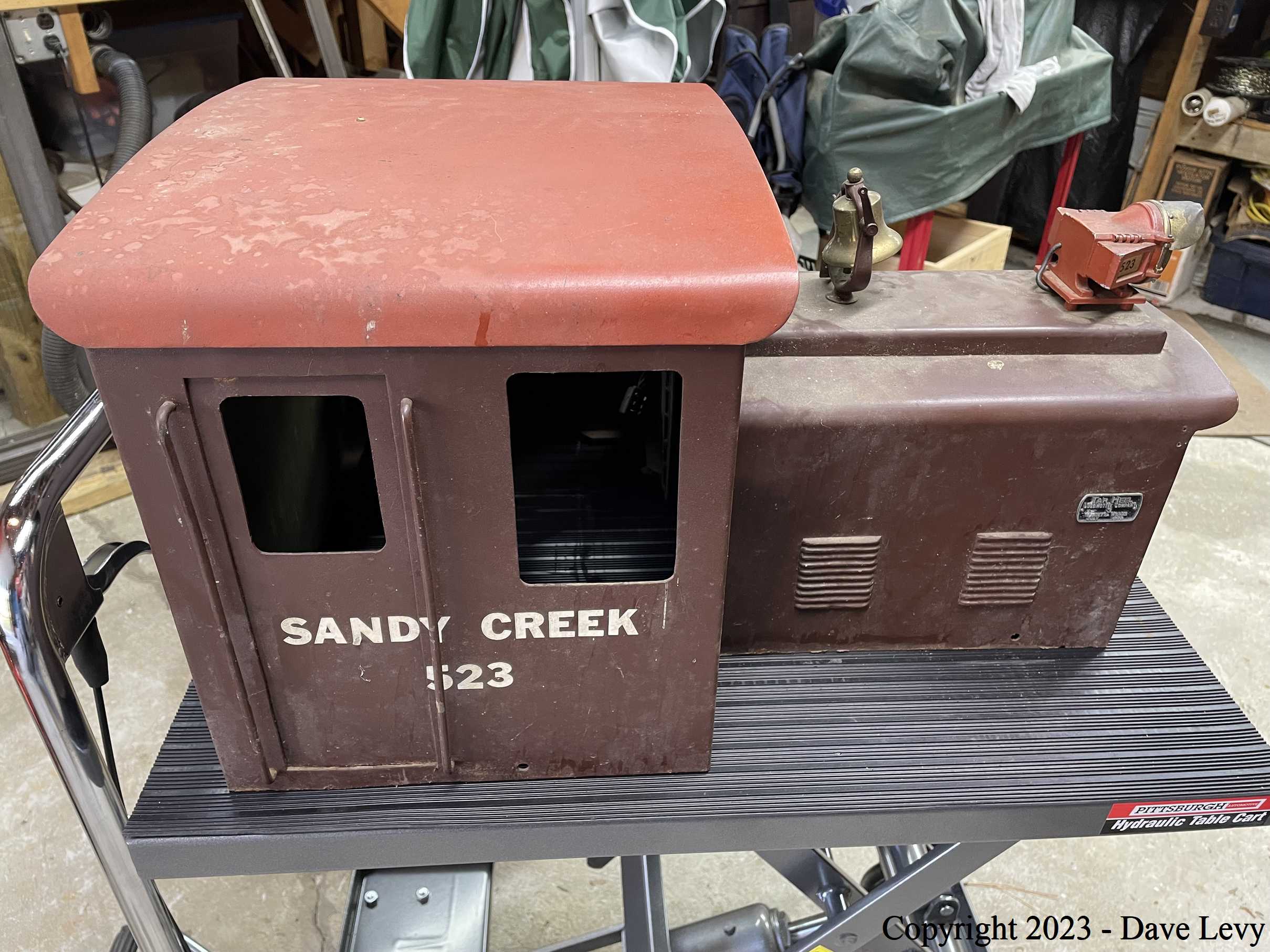
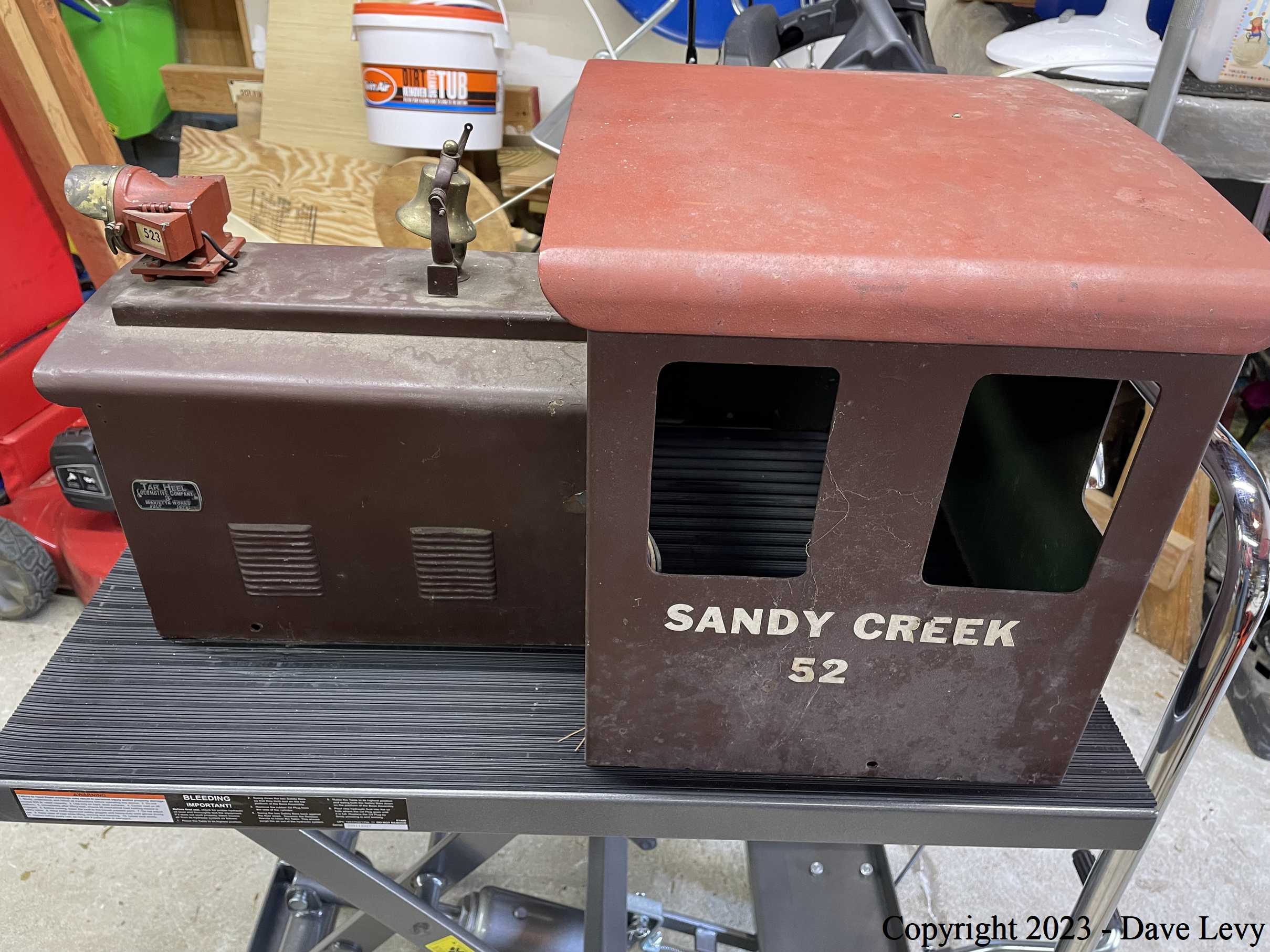
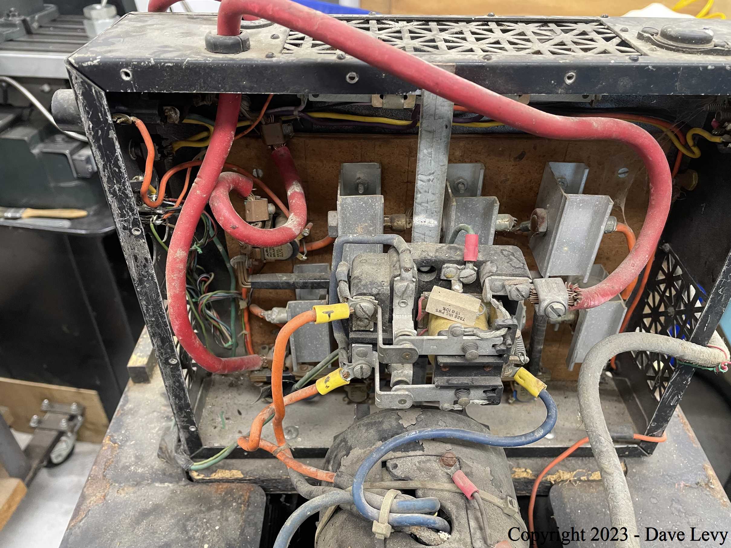
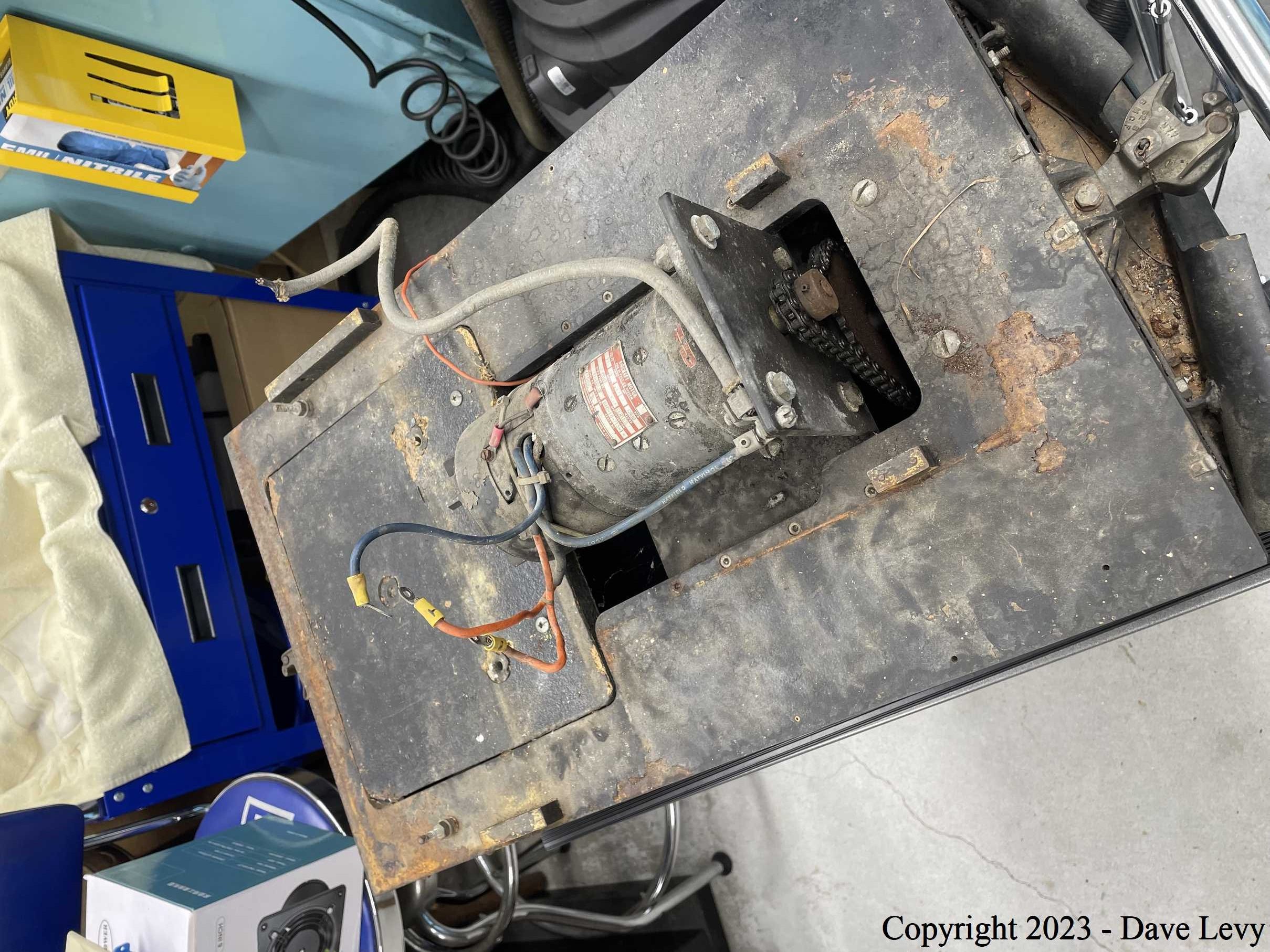
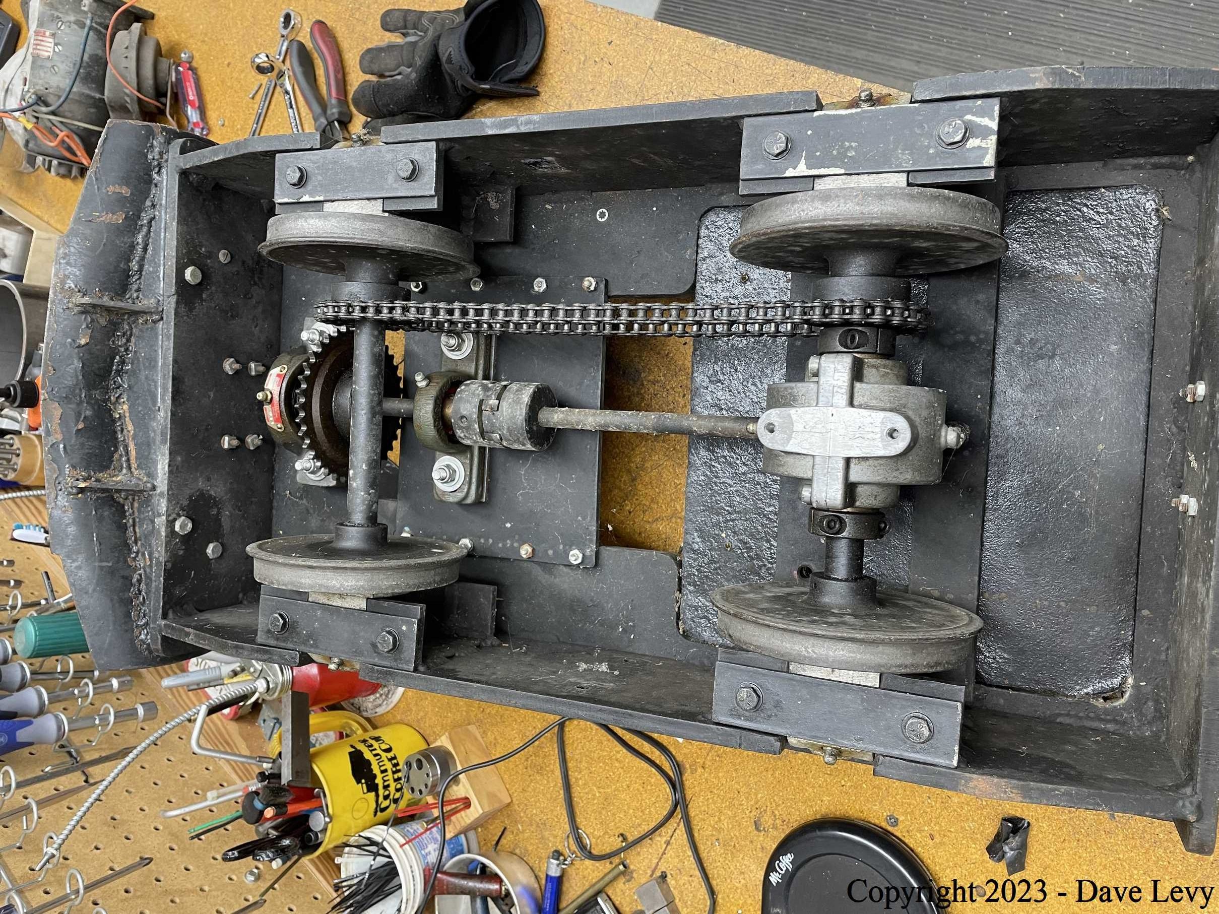
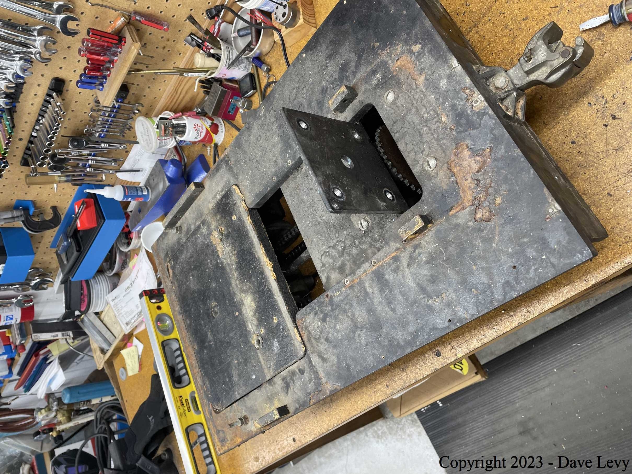
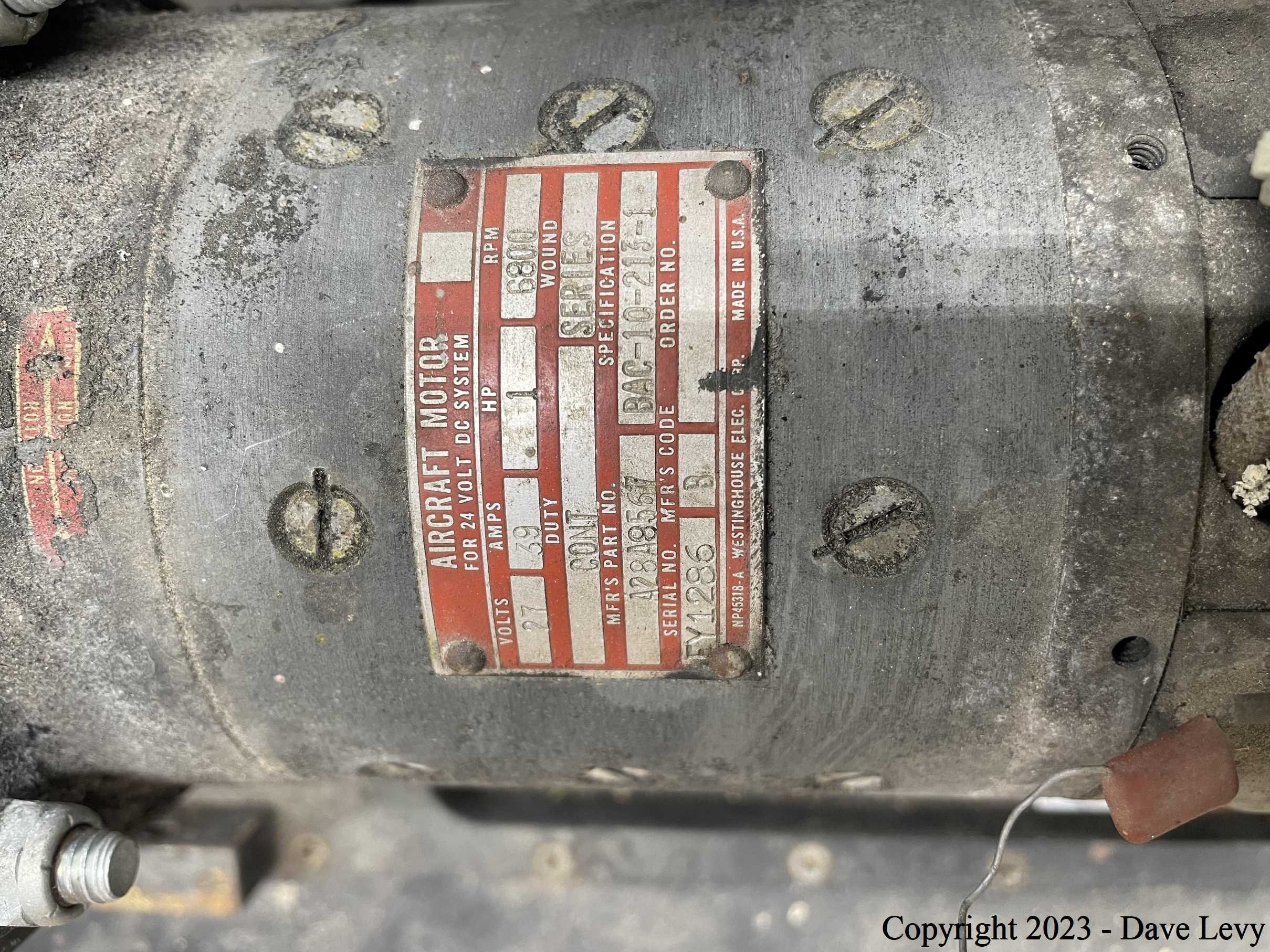
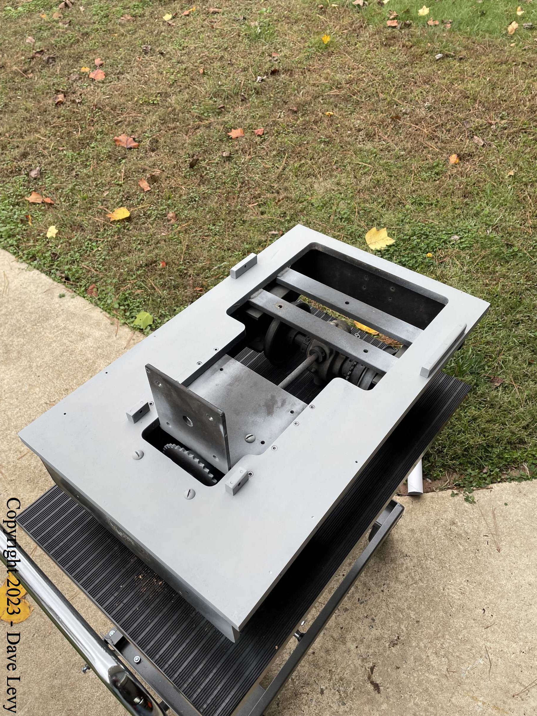
As mentioned, I needed a project, so I purchased the rolling chassis from Darlene in late November 2023. Once I got it home, I disassembled it all, taking pictures along the way, to see what I had and what I could reuse. Fortunately, the wheels, axles, and other running gear were all in good condition. They just needed a little clean-up, paint, and grease to be made functional again (more on this later). The cab was also in great condition and just needed a fresh coat of paint. Even the builder’s plates were in good shape and could be restored. As expected, the electronics to control it were totally shot. It had a tethered control box attached to a homemade power distribution module. I knew it didn’t work before purchasing it and was planning to replace it all with a modern RC control system.
Here are some pics of the original parts before and during disassembly.
Electronics
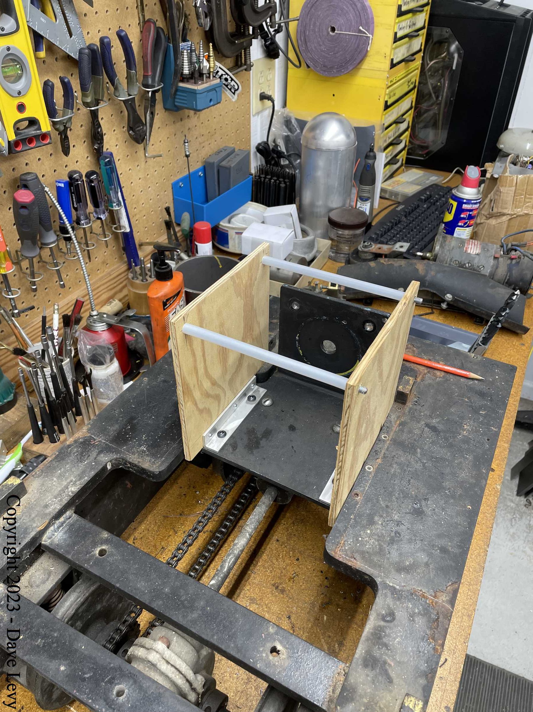
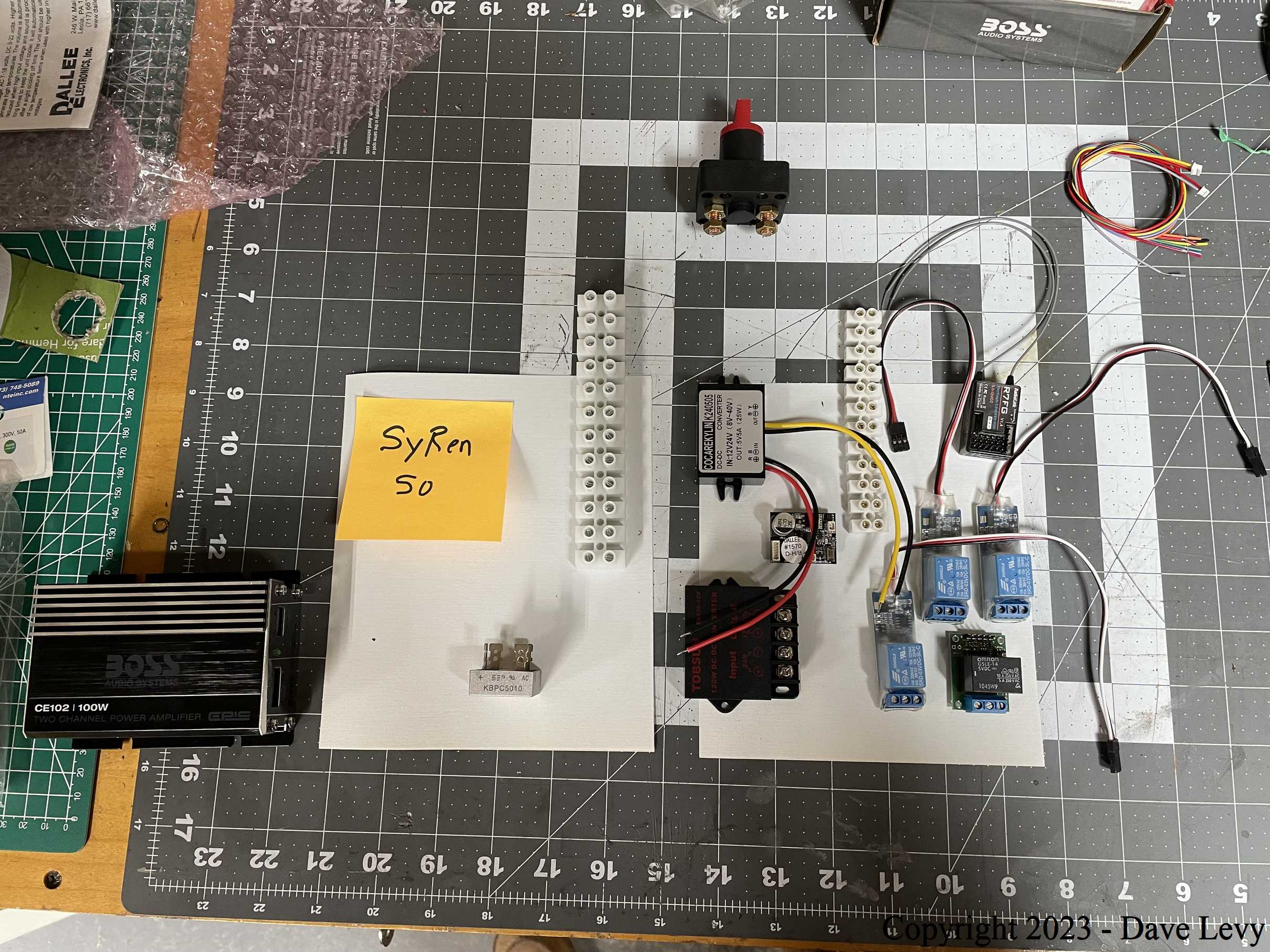
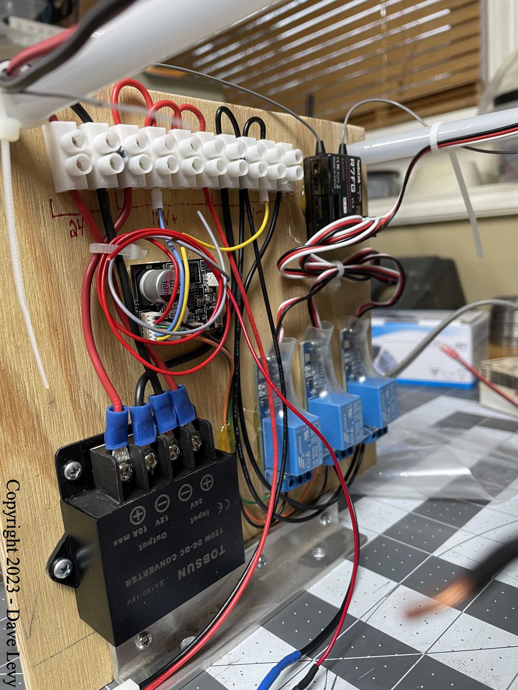
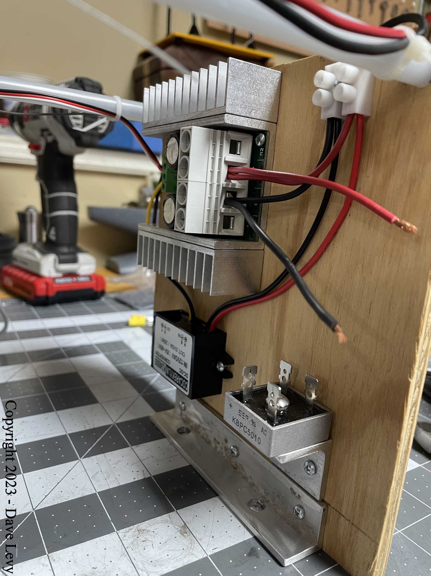
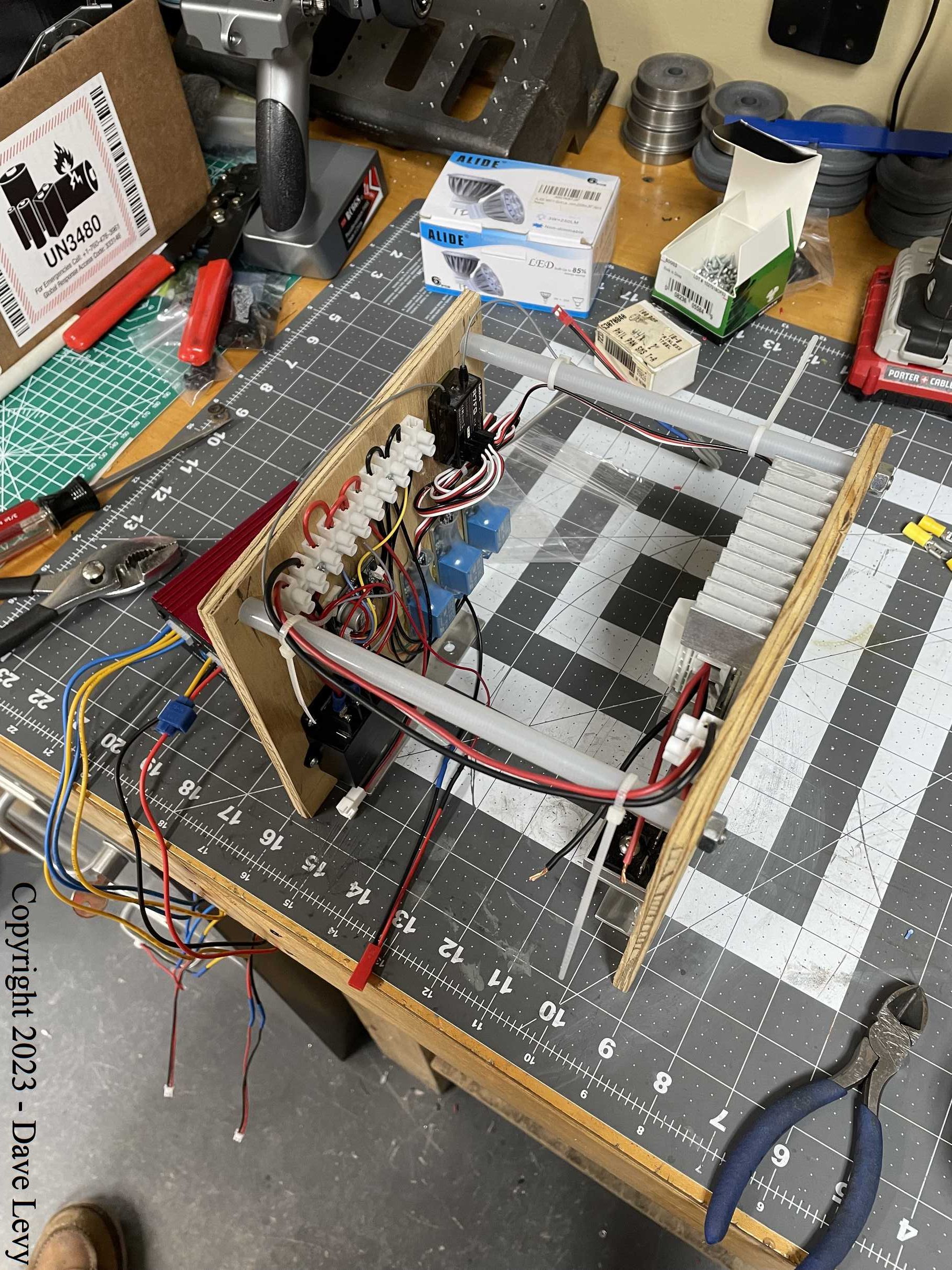
Once I had the chassis stripped and knew what I had to work with, I set about designing and building the new electronics package. I discovered fairly early that the series-wound 1hp electric motor that came with it was not going to work well with a modern PWM (pulse-width-modulation) electronic speed control (ESC). The ESC is designed to work with permanent magnet motors so a suitable replacement was obtained from eBay. It is also 1hp running on 24V so it should have plenty of muscle. I settled on a SyRen 50 ESC as I also use it on my other switcher. The rest was just a case of organizing it onto two plywood back panels that would sit one on each side of the motor. Here some pics of the setup.
Mechanical Restorations
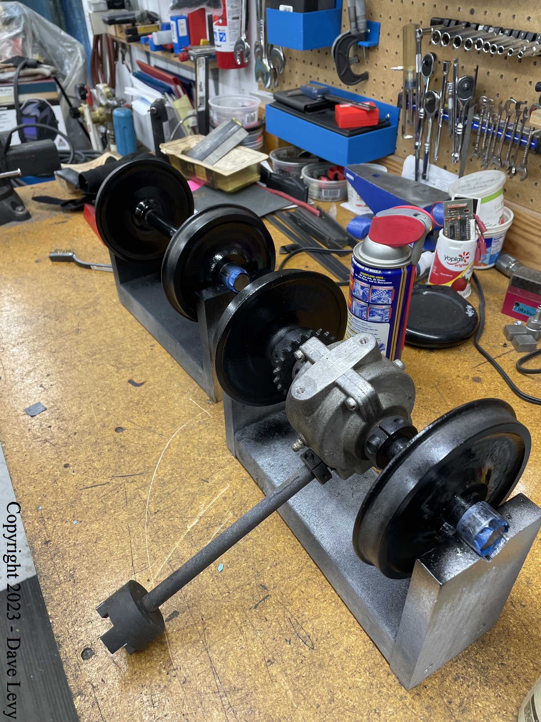
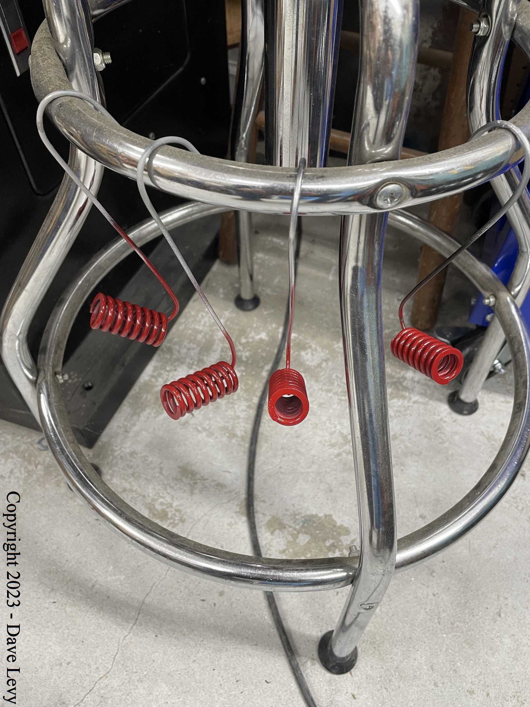
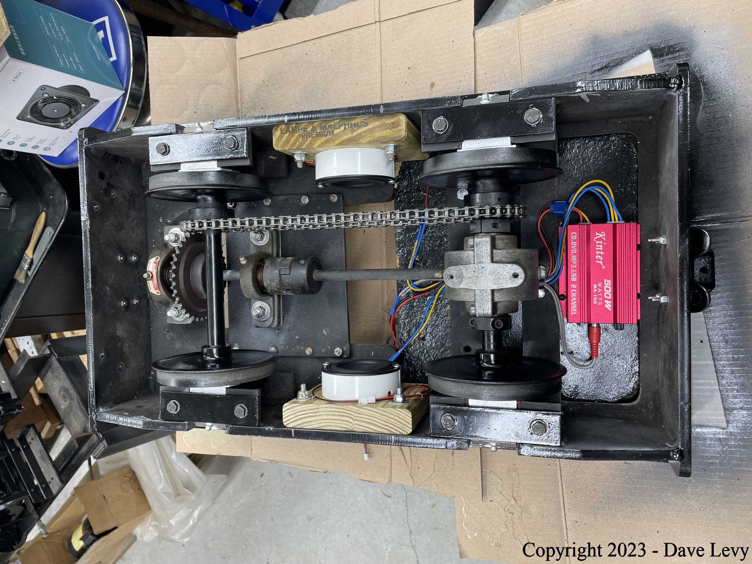
The mechanical parts of the loco were, for the most part, in decent condition. I removed the wheel sets, leaving the wheels on the axles, and inspected the journals and bearings. All were in good condition and just lacked some fresh grease. The drive chains were worn and dirty so they were replaced. The “gearbox” was fine and ran smoothly so it just got some fresh grease.
Paint Paint Paint
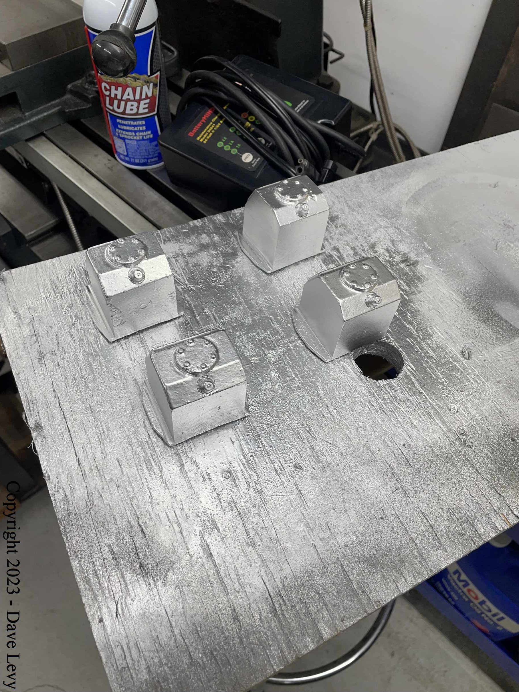
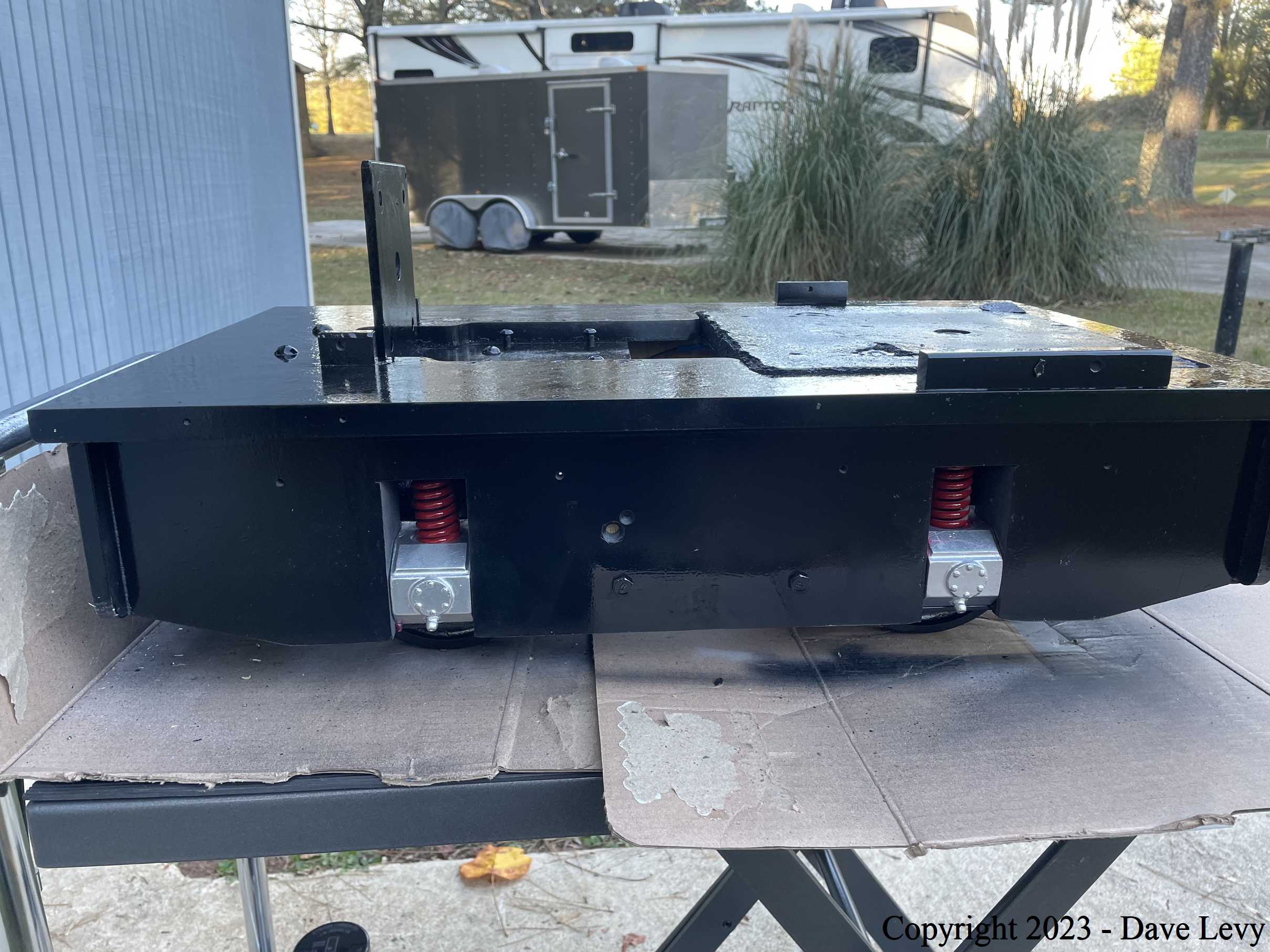
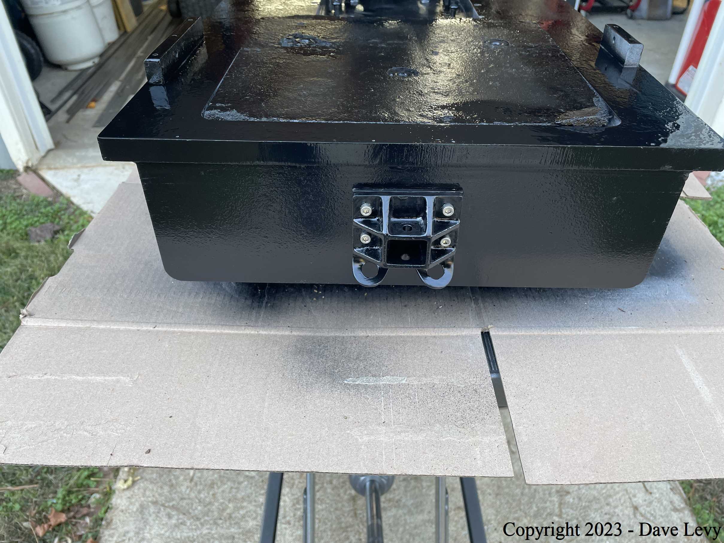
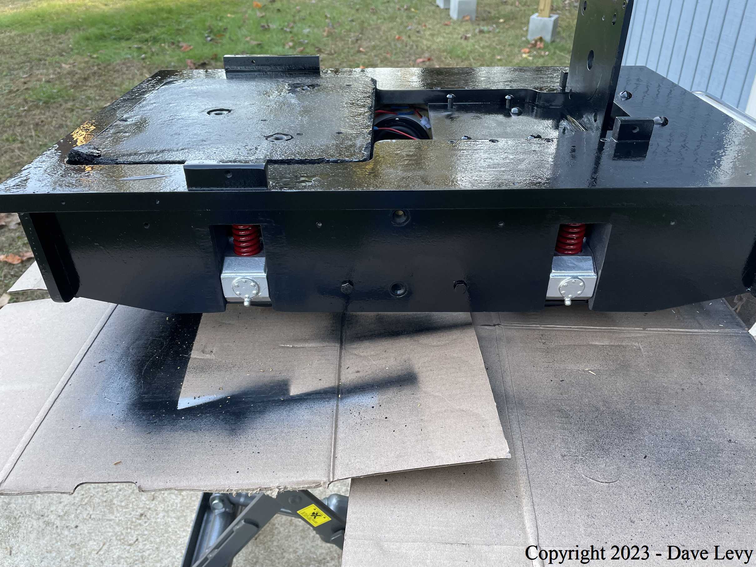
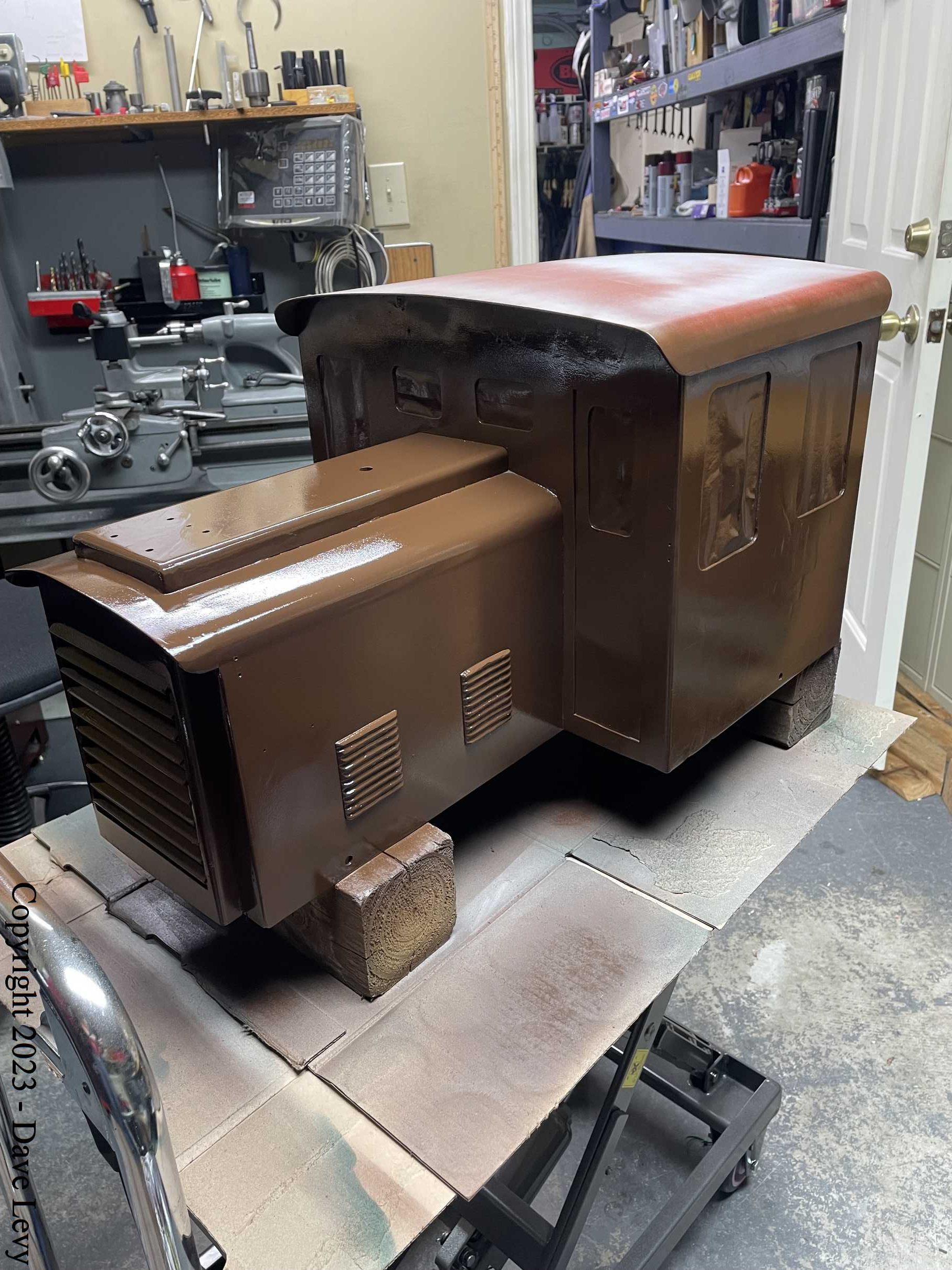
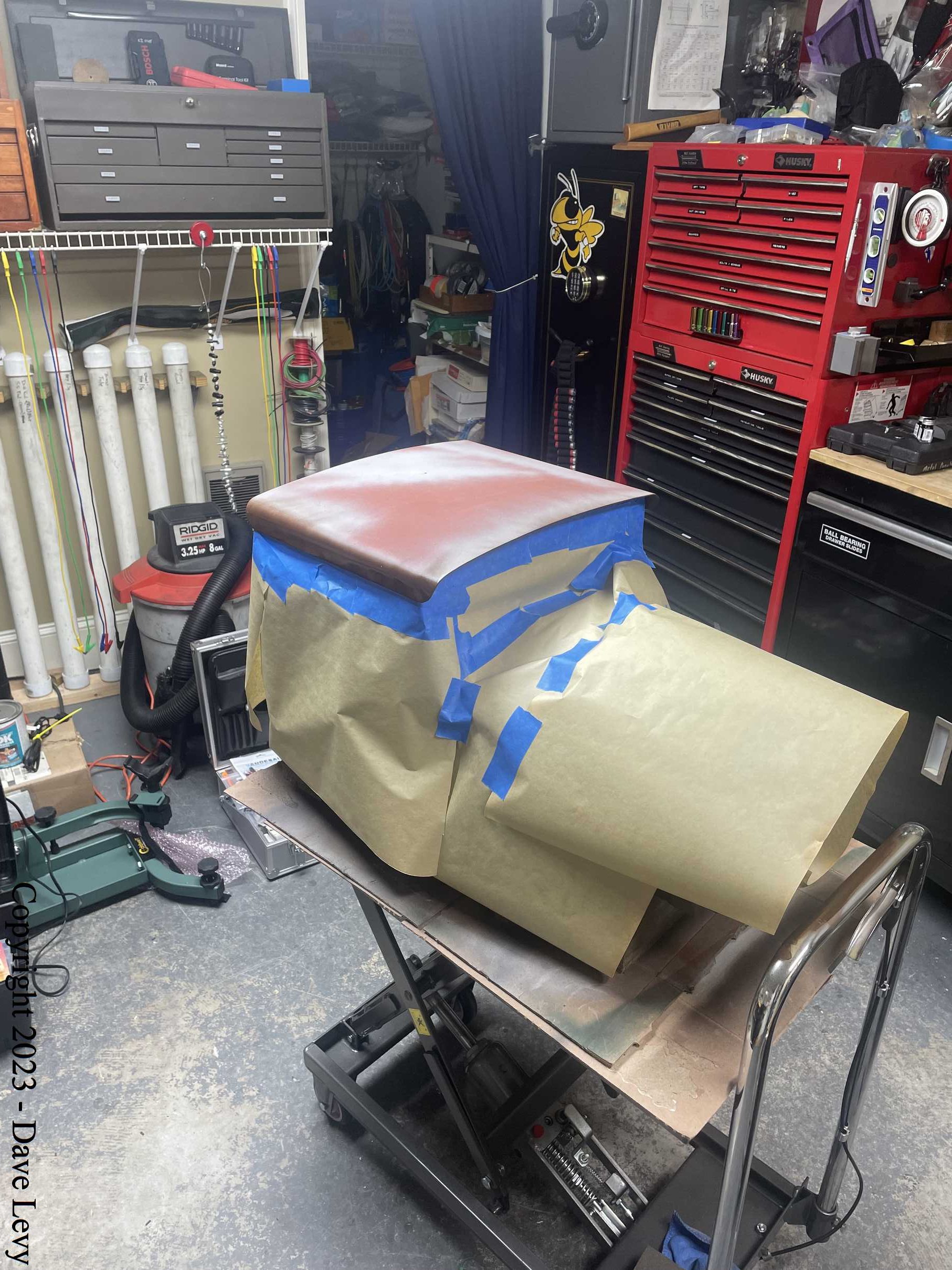
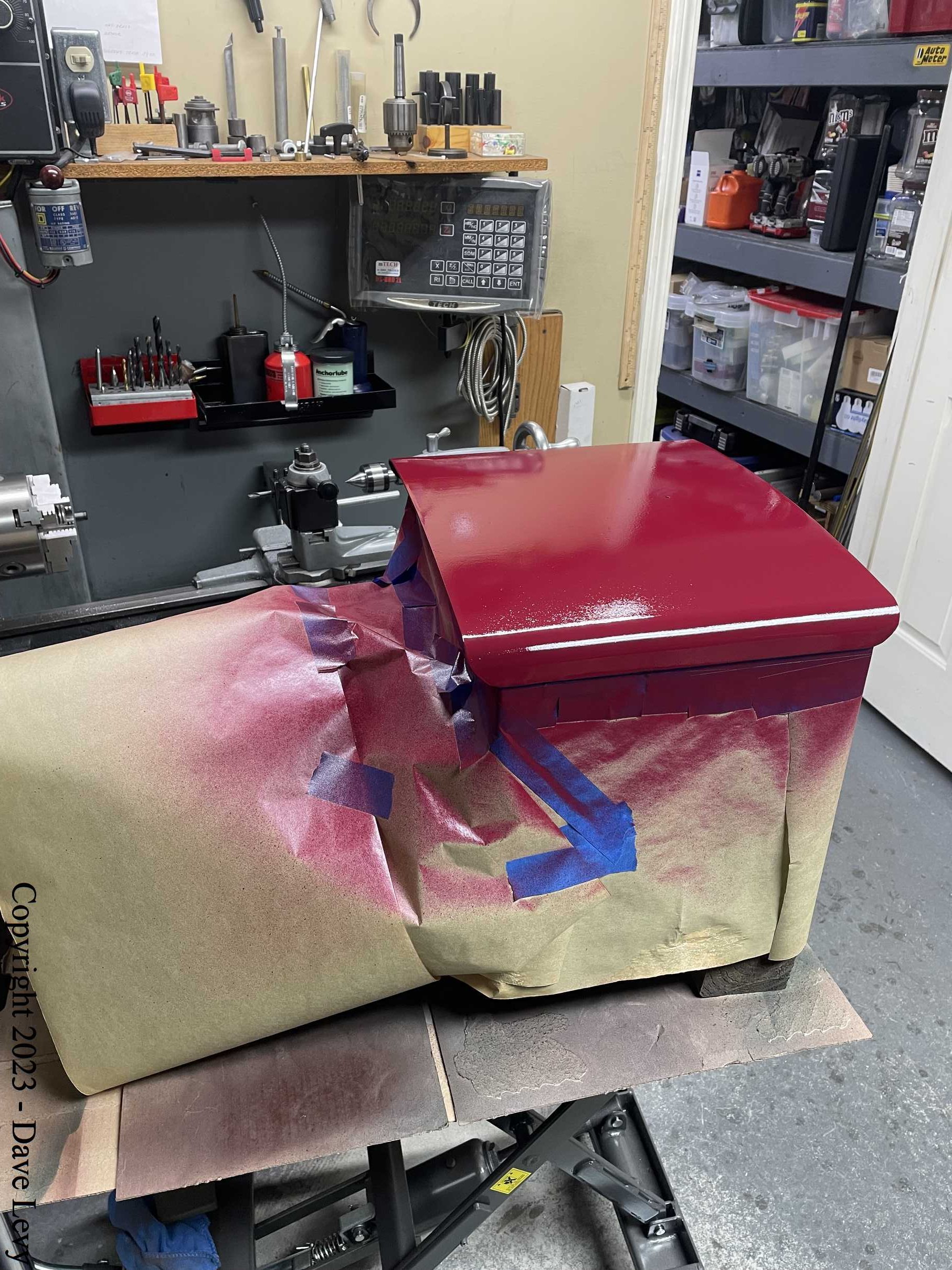
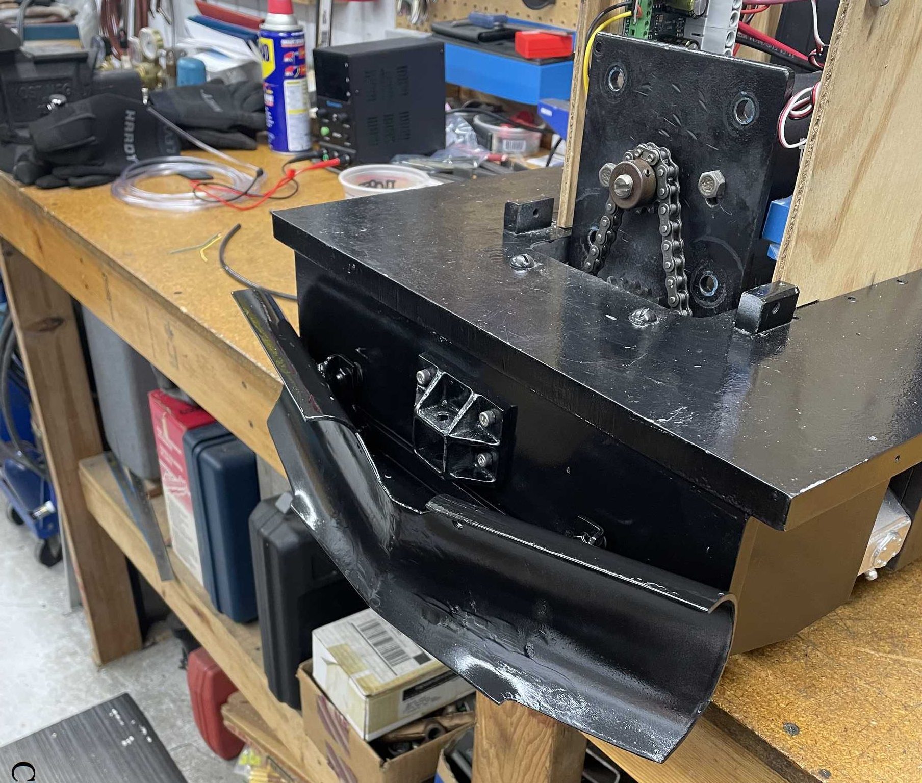
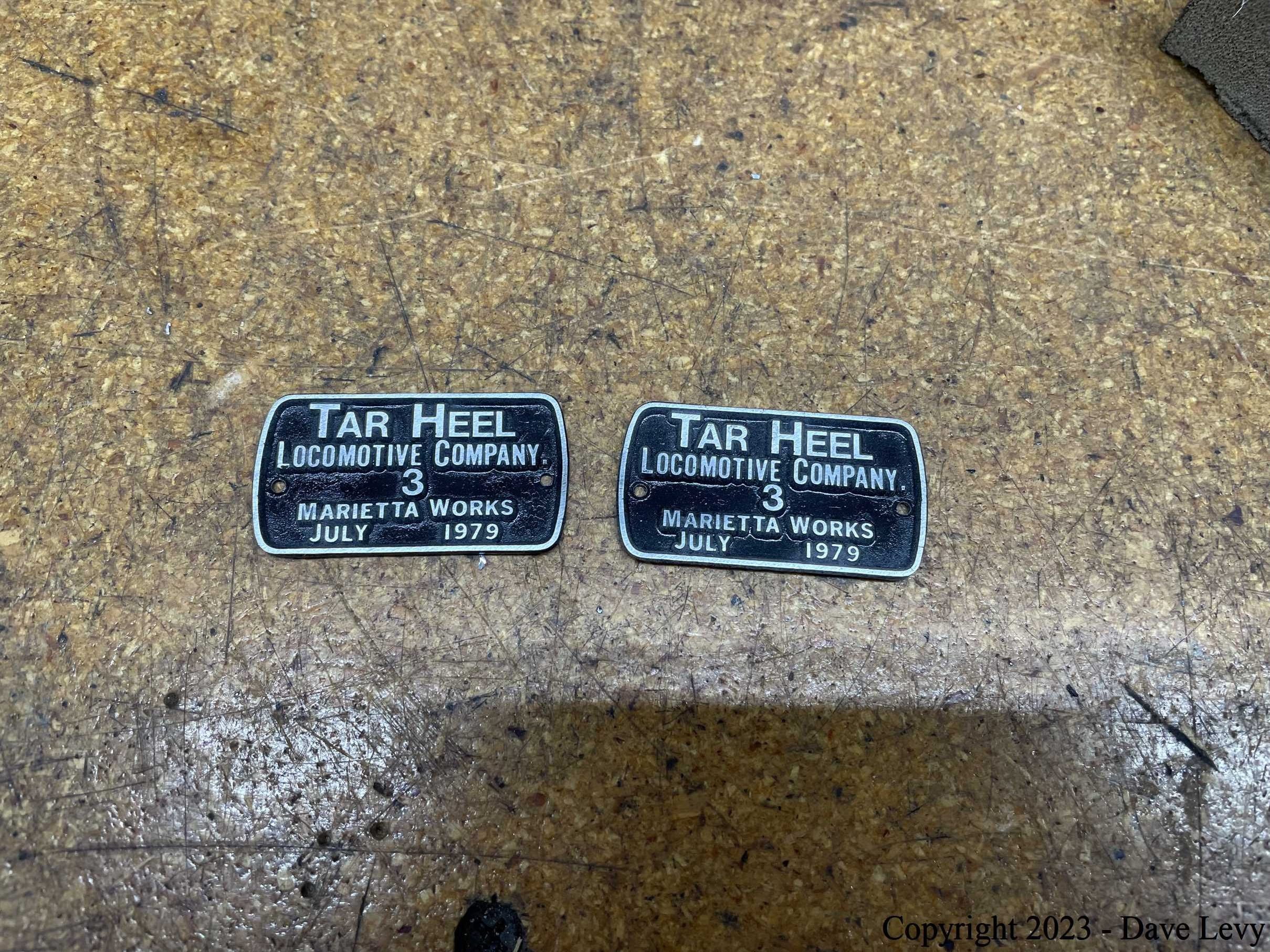
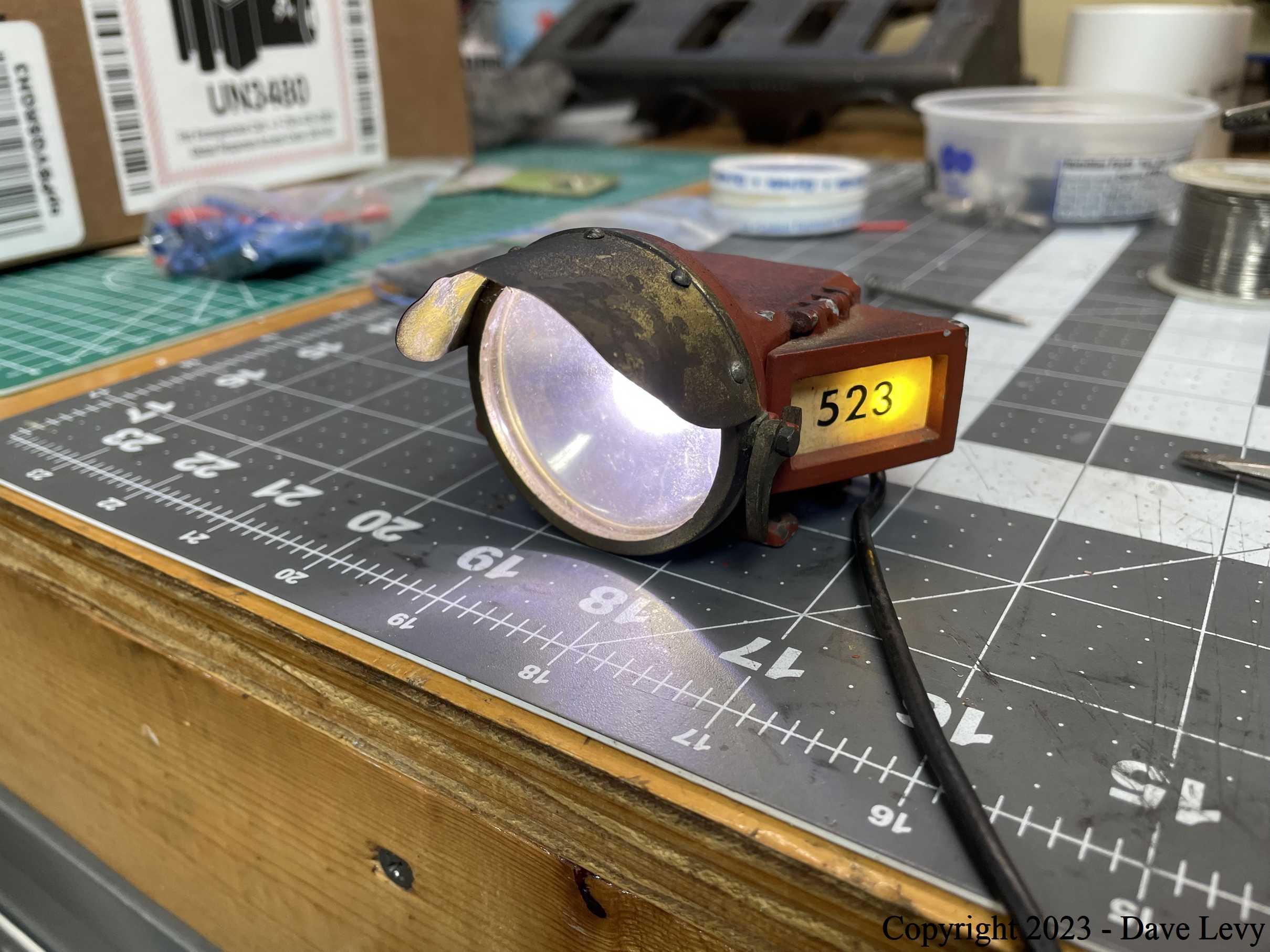
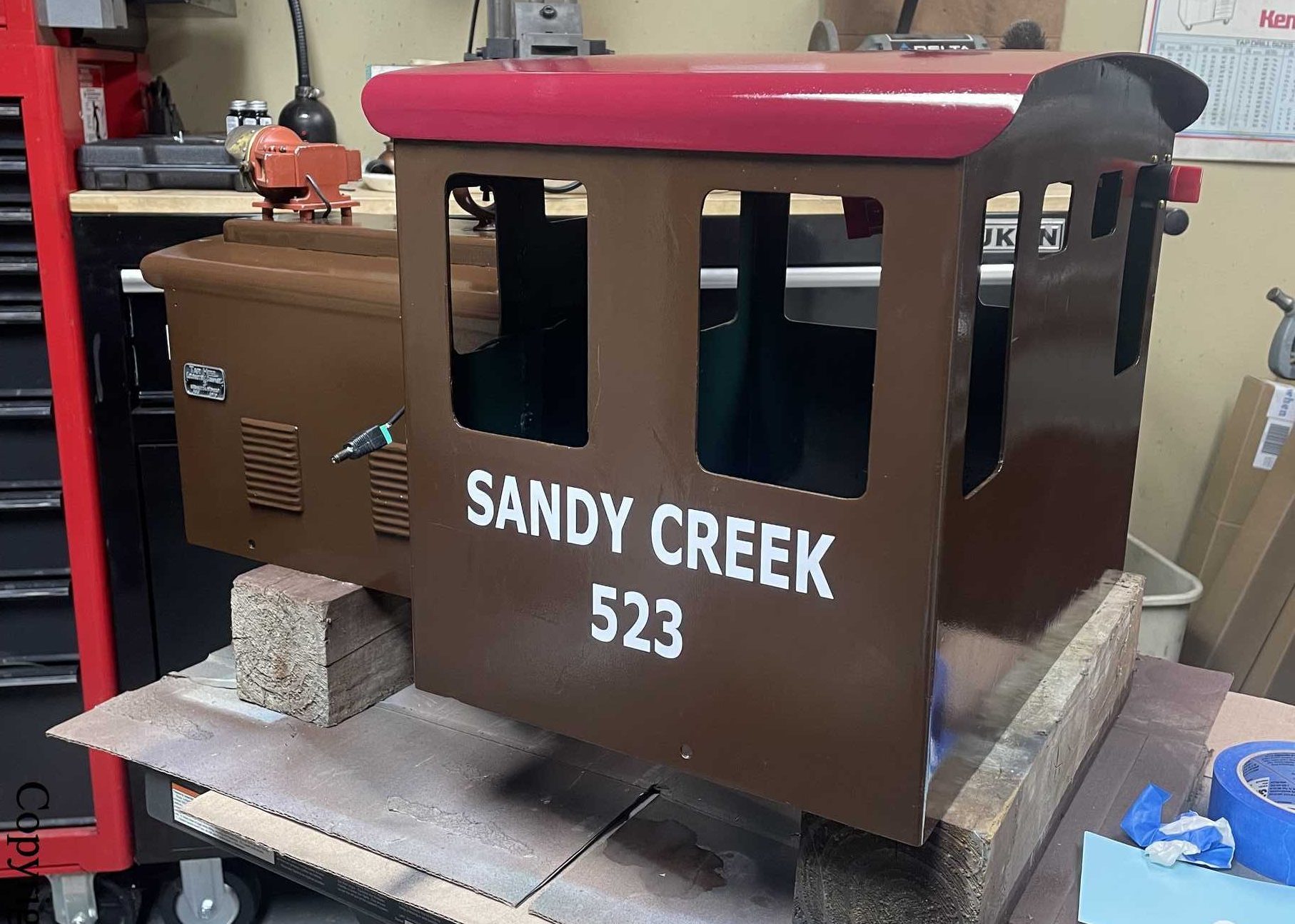
Truth be known, I do not like painting all that much. Unfortunately, it is the part that most people see when they see your locomotive, so it has to be done fairly well. Even the original builder’s plates were repainted and restored. Here are some pics of that process.
Assembly
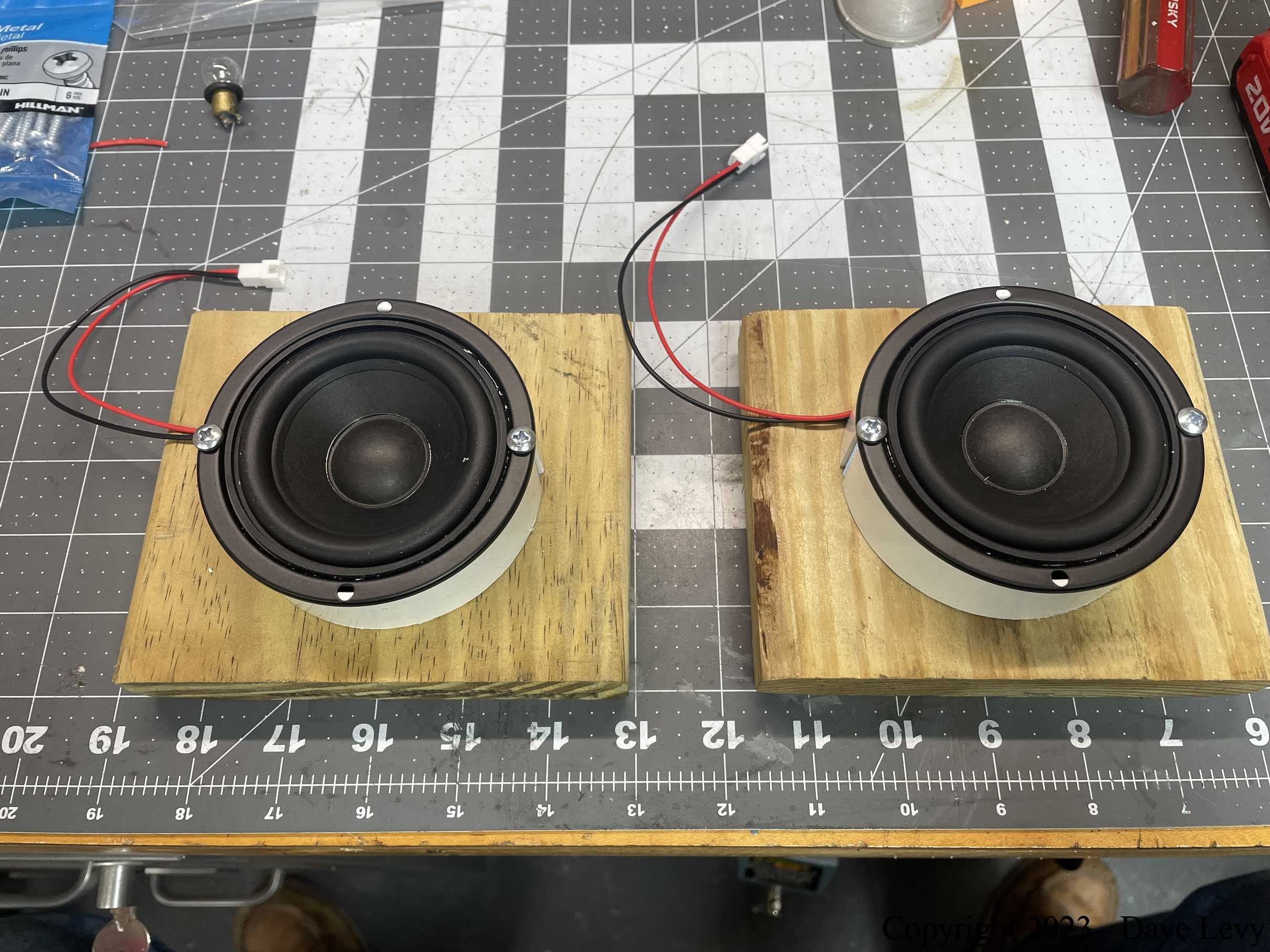
Once everything was painted and all the components were assembled, it was time to put it all together on the chassis. The speakers and amp for the electronic bell and horn were installed on the underside of the chassis. The control electronics, as mentioned, sit on either side of the motor. A few connectors and a 100A circuit breaker round things out. Here are some pics of this.
Transport and testing
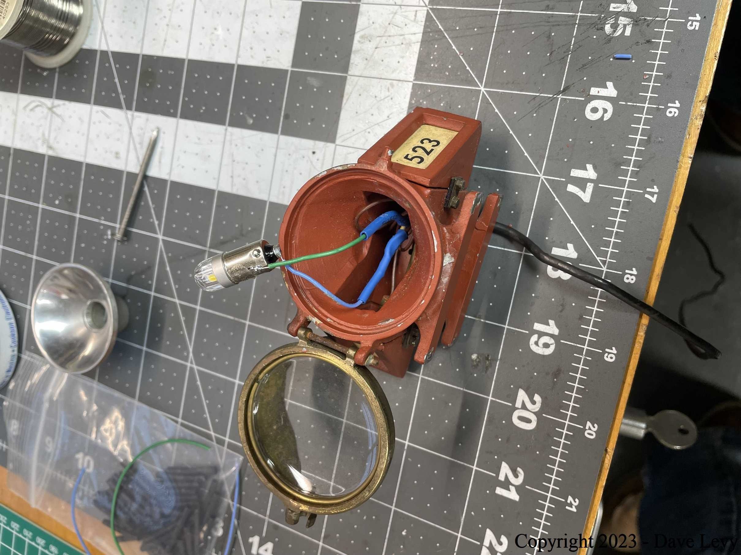
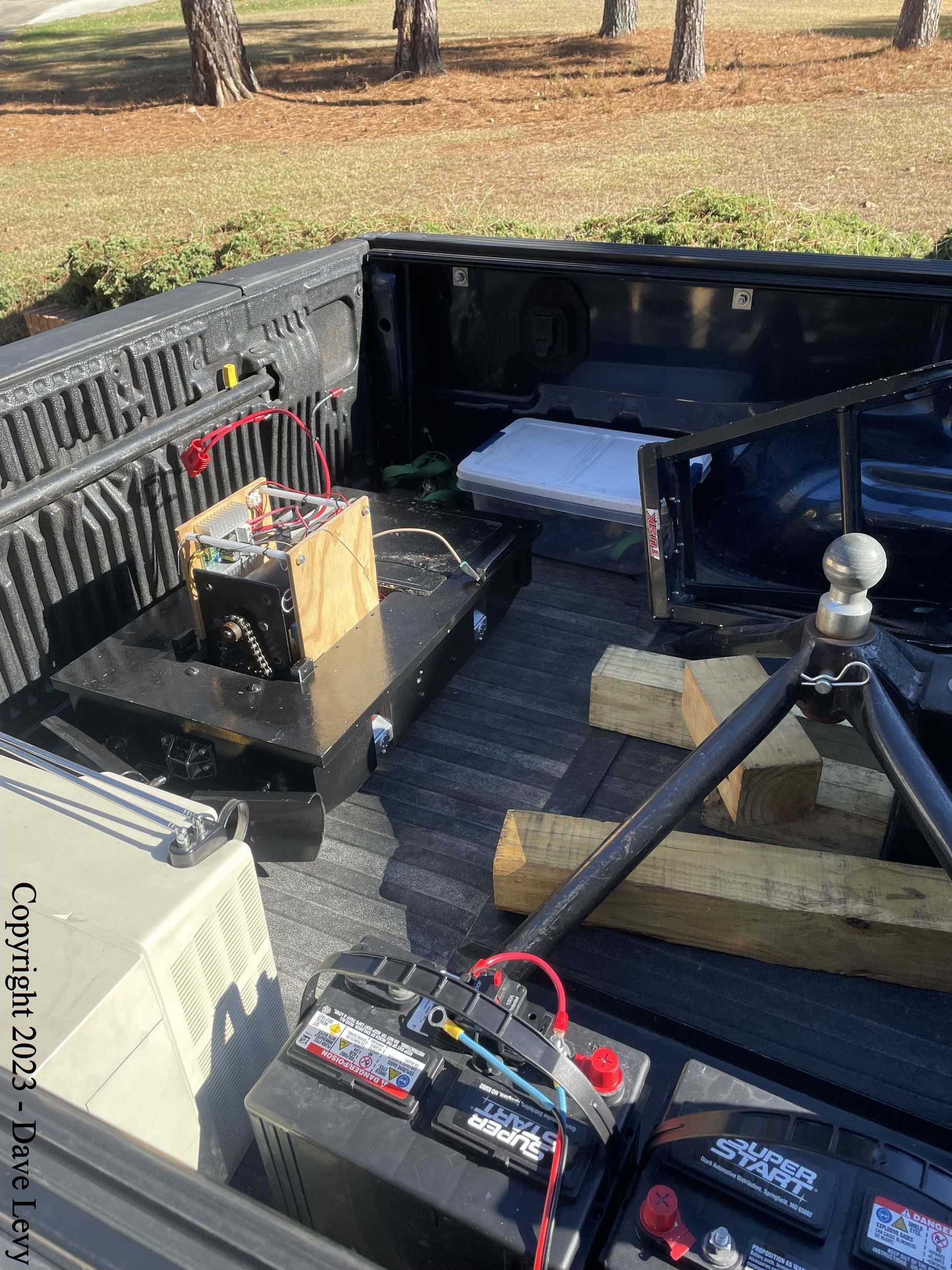
The partially disassembled switcher was transported to the club track for final testing. It all went very well. Everyone that attended the event was pleased with how it ran. One minor issue with the headlight was noted and corrected a few days later.
Final Thoughts
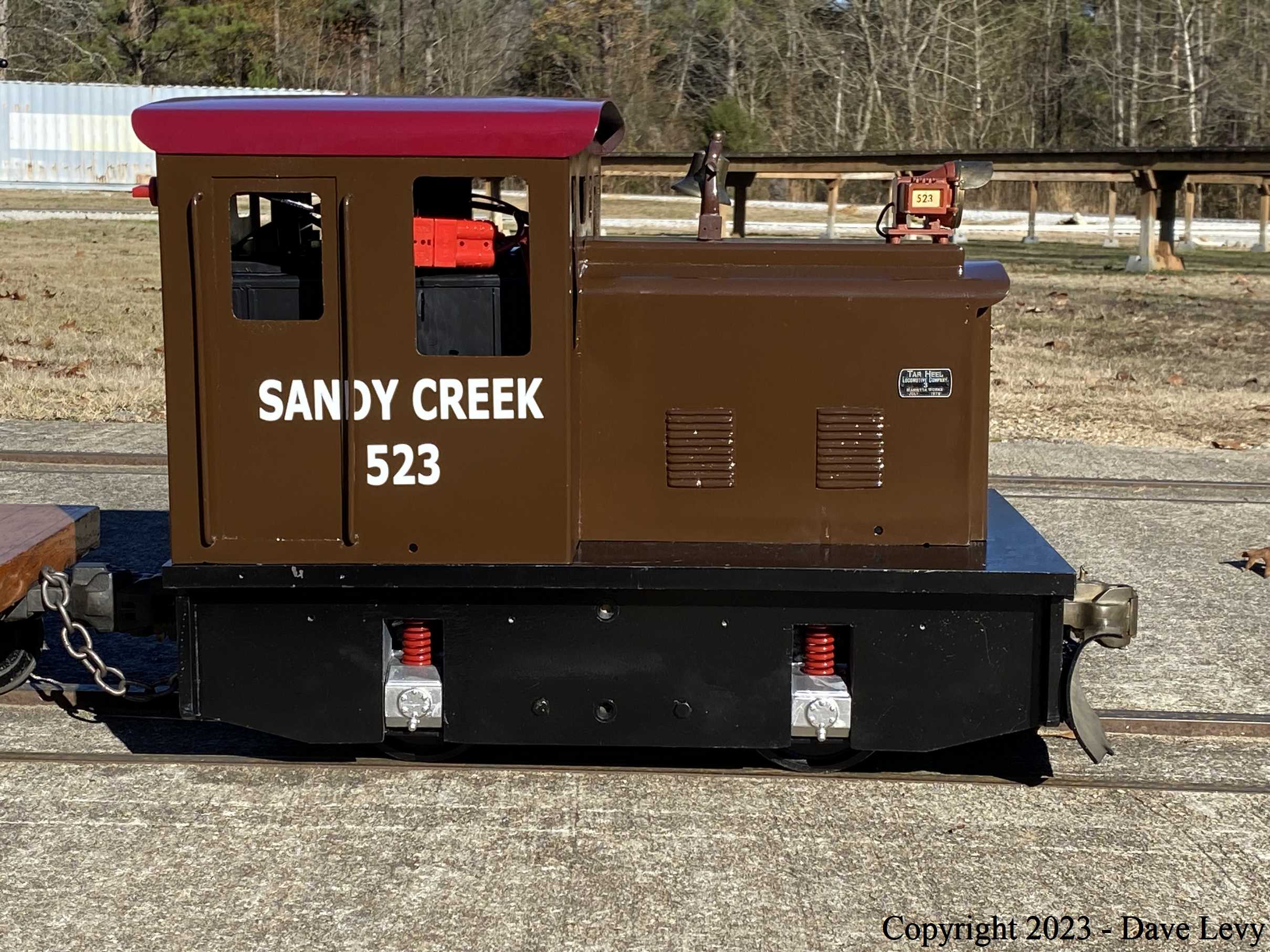
Altogether, the restoration took about 2-1/2 weeks. About a third of that was spent either waiting for parts to arrive or waiting for paint to dry. It was a fun project that, overall, went very smoothly. I am happy with the end product. Since I don’t have any real need for it myself, I will be looking for a buyer very shortly.
Here is a video clip of some of what went on during the restoration as well as the final testing. Enjoy!
