Dateline: January 2004: I’ve decided to try my hand at a small all-electric engine. I chose the little Plymouth switcher just because I liked how it looked. The project is well underway as you will see from the pictures shown below. I obtained a pair of 24VDC electric wheelchair gear motors from eBay at a reasonable price (I think). I welded up a chain sprocket such that I can lash the two motors together as a tandem unit. This should provide more than enough horsepower to propel the little engine quite nicely. A friend, that can weld aluminum, welded a couple of pieces together to form the bed. Another friend had an unused (and unwanted) start to a power truck also all in aluminum. So that was the start. For a controller, I chose the Pro-150 from 4QD, a company in England, that manufactures a wide variety of pulse-width-modulation (PWM) type controllers. This one will handle up to 150 amps at 24VDC without any problems. The controller is pretty nifty. Aside from the obvious, it provides dynamic braking which actually charges the batteries when it is coasting downhill. This will extend the running time significantly. The locomotive will have a pair of 12V marine deep-cycle batteries on board.
4/4/2004
I have most of the parts fabricated for the running gear part. I assembled the entire power plant and took it to Wayne’s track for testing. It performed very well with only one derailment most likely due to a “wave” in the track and the fact that the suspension is still very stiff and lacking proper lubrication. I took a couple of pictures of the event as seen below. I’ve also included a number of other pictures of various parts of the construction thus far.
Summer 2016
I purchased a sound system from John Boots and added it to the switcher to give it some life. The sound system now provides the bell and horn so separate units are no longer needed. I rigged it so that I can turn it off when I want to run silently.
 Base
Base


November 2019
The lashing together of the two motors has turned out to be a bad idea. They did work this way for 15 years but, in the end, the motor shafts were not perfectly aligned and eventually caused one of the shafts to be worn away so that it failed. I reversed the motor positions to use the other end of each output shaft and this time used a separate sprocket on each shaft. The chains drive the same idler shaft but no longer have to be in perfect alignment. This method should work indefinitely.
February 2020
Interestingly, once I corrected the drive system (see previous update), several nagging issues became more urgent. I discovered that one of the electric motors was intermittently not running. This turned out to be a stuck brush that had lost contact. I made a “in-the-field” repair and have since replaced the brushes. I also got very tired of dealing with derailments because the wheels would not stay in gauge. The set screws were just not up to the task. Even when tight, the wheels had a wobble to them because they fit the axles so poorly. This is what happens when you salvage parts from someone else’s scrap bin and build a loco from it. I have machined new axles with a proper press fit for the wheels and woodruff keys for the wheels and sprockets. That should fix the gauging problem permanently.
 Switcher in action


 Assembled and ready for paint

Stay tuned for more updates!
March 2023
The time has finally come to convert the switcher from tethered control to radio control (RC). I have been wanting to do this for quite some time but was unsure of some of the details. I was able to learn enough at the recent Big Boots and Western meet in Florida to feel comfortable making the change. The current tethered control uses a 4QD control and a rheostat to control the speed. This has been totally replaced with a Dimension Engineering speed control, a Radiolink transmitter and receiver, and a Dallee sound card. All the controls fit neatly on a single piece of plywood. I decided to only change the minimum at this time to make sure I liked it before completely gutting it. It all worked great and I like it a lot. Someday I will gut it out and clean it up.
RC board (simple) 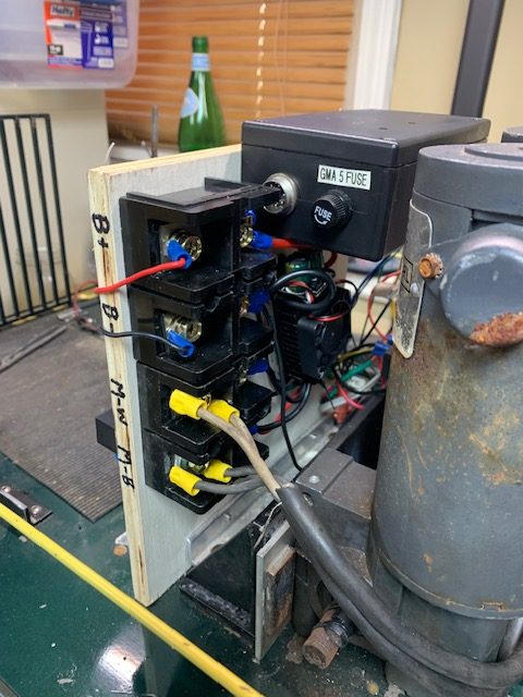
Power connections 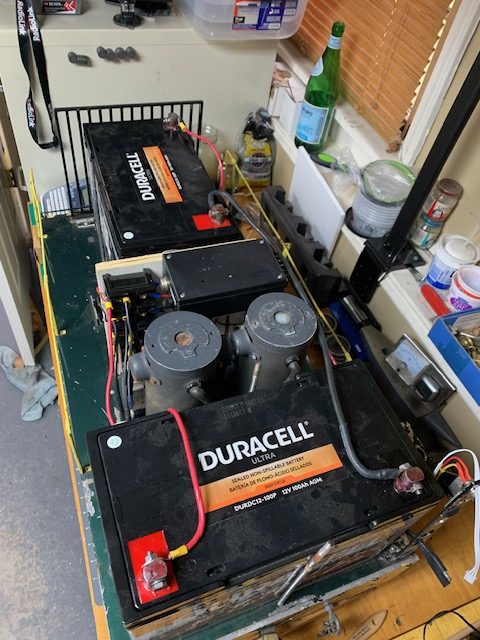
Top view of batteries
March 2024
So it has been almost a year since I converted to RC control. It has been working out very well. It is so much more convenient when throwing switches in a yard to be able to control the switcher remotely. Running it is also much easier and, in my opinion, safer since the transmitter throttle is spring loaded and shuts off if I drop it or fall off the locomotive. I have been having some issues with the motors though. They seem to get hot quite easily. I am not sure if they are finally failing (I bought them used 20 years ago) or if something else is wrong. In any case, I had promised myself that someday I would gut it out and clean all the wiring up. Since I need to take it apart to diagnose the motors, now seems like a good time.
I discovered that the brushes in the motors where not making full-width contact. The brush holders seem to be misaligned. I suspect this may have happened when I did the emergency fix back in 2020 and it has finally gotten serious enough to make it noticeable. I re-aligned the holders and got new new brushes for it. Hopefully, that will fix it up. I also found one of the original chain sprockets was totally worn out so it was replaced as well.
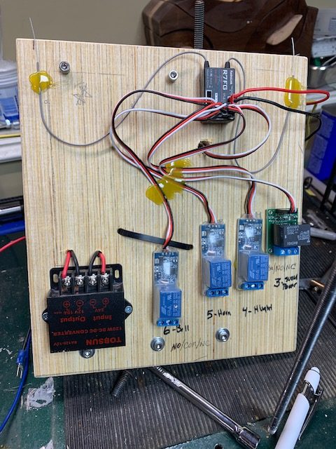
I gutted all the wiring and completely remade the RC board. It now has the sound card mounted directly on it. It also has a larger 24V to 12V converted as well as a 12V to 5V converter that is used to power the RC relays. Bus bars were added to make things neat and tidy. It looks much different now but it now totally self-contained. Only the batteries and motors are external to the board.
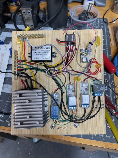
Revised RC control board
Hopefully all these changes will make it run better and last a good long time yet.
December 2024
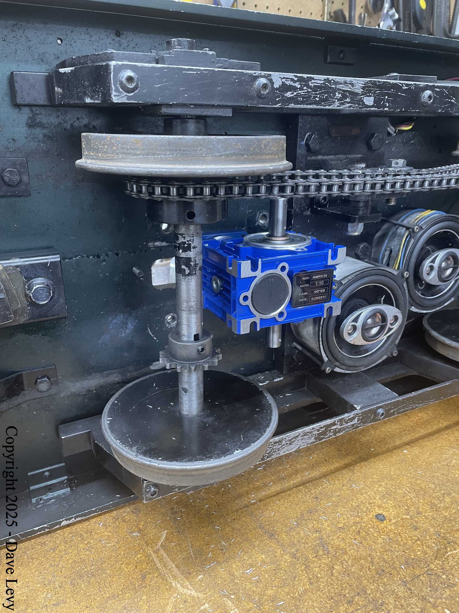
The motors have finally given up. They draw a lot of current but have almost no torque left. The windings seem to be ok when I tested them so I am thinking that the magnets have degraded from time and heat. After doing some research, I found a 2.1HP permanent magnet motor that will run at 24V and a 10:1 speed reducer to adapt it to the wheel speed I need. I designed a mounting plate system for it and had it cut at SendCutSend.com. They did a nice job and it fit perfectly. It was a bit tricky to install but I finally got it. It will be stress tested at the Big Boots and Western meet in late January 2025.
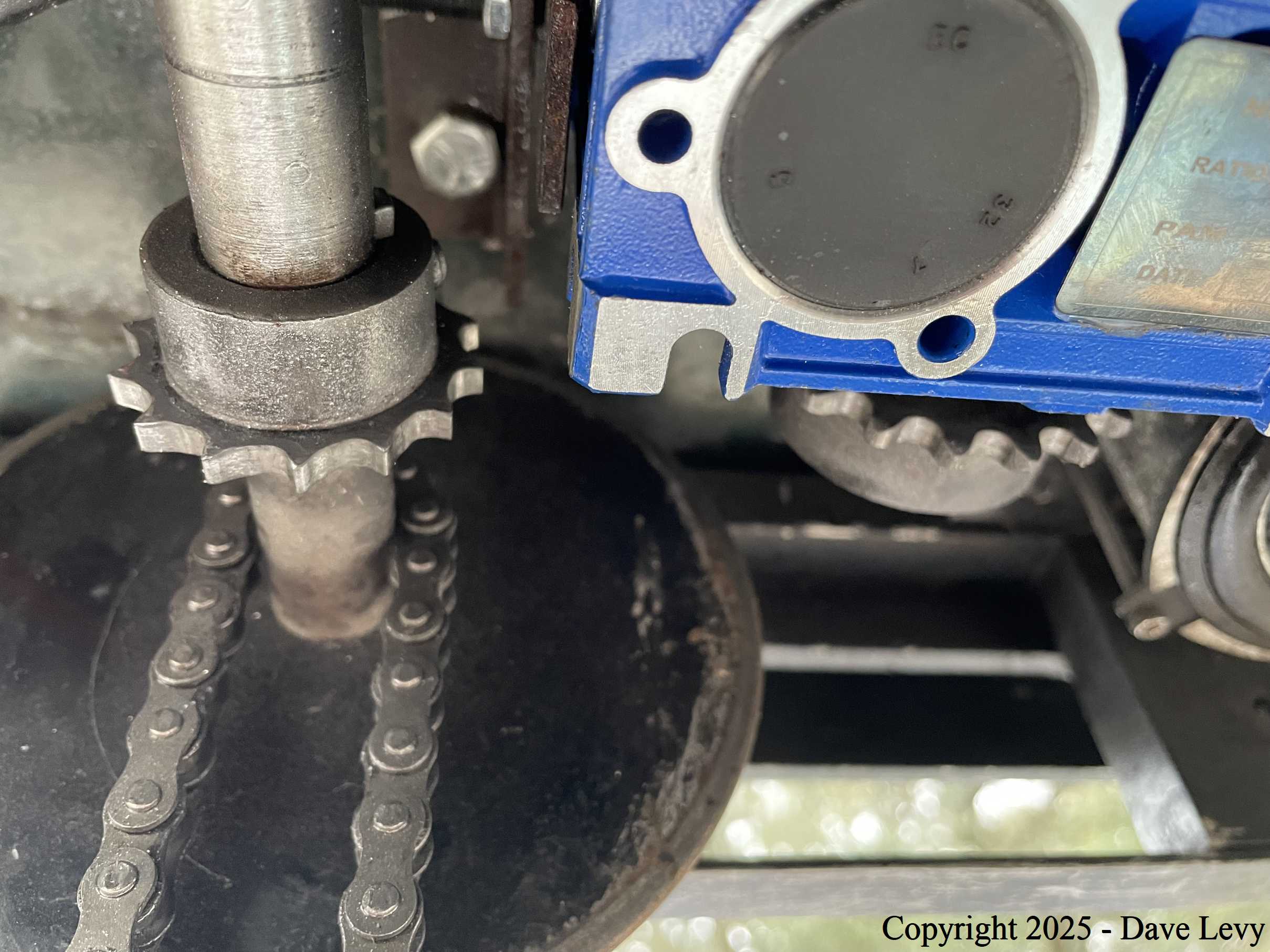
January 2025
Initial testing at the BB&W meet went well. It pulled well but soon developed a weird clunking sound as if the drive chain was binding or somehow skipping. Inspection revealed that the motor/gearbox combo had twisted on its bolts (sloppy holes!) so the sprockets were now misaligned. Adjusting and tightening was not enough to keep it from recurring. Using rather primitive tooling, I was able to fashion a brace using exiting tapped holes that allowed me to utilize long “set screws” to reinforce the gearbox and keep it from twisting. This seemed to work but the sound soon came back. When I removed the drive chain for another inspection, I realized the root cause of the problem…the driven sprocket’s teeth were worn down to nubs. The chain slack was enough for the chain to crawl over the nubs under load. A new sprocket was ordered and upon arrival, the axle was removed, a wheel pressed off the end, the new sprocket was installed, and the wheel replaced. After reassembly of everything, it ran perfectly for the rest of the meet. I could tow anything I wanted and had enough torque to spin the wheels on demand. I am well pleased with it now.